


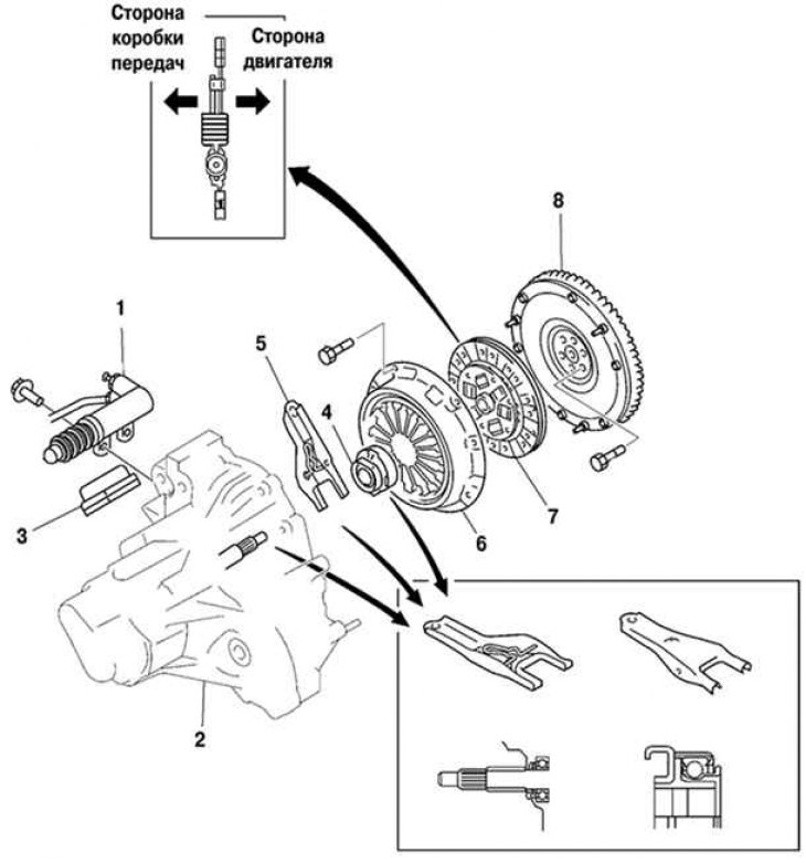
Fig. 3.11. Removing and installing the clutch: 1 – clutch release drive slave cylinder; 2 – gearbox; 3 – fork cover; 4 – release bearing; 5 – clutch release fork; 6 – clutch housing; 7 – driven clutch disc; 8 – flywheel
Removal
Remove the gearbox in block with the main gear.
Remove the clutch release fork boot.
Remove the clutch release fork assembly.
Remove the clutch release bearing sleeve clamp.
Remove the clutch release fork support from the gearbox.
Loosen each bolt one turn at a time until the spring force is released.
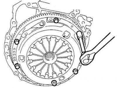
Fig. 3.12. Removing the clutch housing
Unscrew the bolts and clutch housing (Fig. 3.12).
Caution! Protect the clutch disc, pressure plate and flywheel surfaces from oil and foreign objects.
Using a special tool, remove the transmission input shaft support bearing.
Note: Do not remove the transmission input shaft support bearing unless you are replacing it.
Install a special device to hold the flywheel from turning.
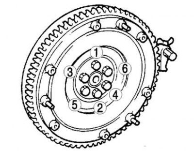
Fig. 3.13. Removing the clutch flywheel
Loosen the flywheel mounting bolts in the sequence shown in Figure 3.13.
Examination
Check the clutch housing.
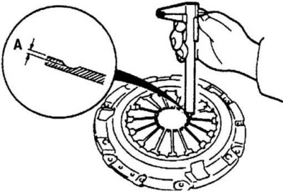
Fig. 3.14. Measuring the wear depth of the diaphragm spring petals
Using a caliper, measure the wear depth of the diaphragm spring petals (Fig. 3.14).
Maximum permissible wear in depth A: 0.6 mm.
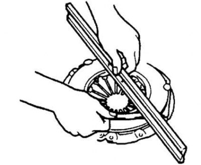
Fig. 3.15. Measuring the gap between the pressure plate and the ruler
Using a ruler and feeler gauge, measure the clearance between the pressure plate and the ruler as shown in Figure 3.15.
Maximum gap: 0.5 mm.
Install the dial indicator on the cylinder block.
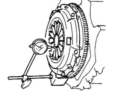
Fig. 3.16. Measuring the deviation of the petal tops of a diaphragm spring
By rotating the flywheel, measure the deviation of the tops of the diaphragm spring petals (Fig. 3.16).
Maximum deviation from plane: 0.6 mm.
If one of the measured values does not correspond to the established standard, replace the clutch housing.
Check the clutch slave disc.
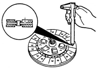
Fig. 3.17. Measuring the friction linings of the driven clutch disc
Using a caliper, check the thickness of the friction linings on both sides of the release disc in relation to the rivet heads (Fig. 3.17).
Minimum overlay thickness: 0.3 mm.
If the lining thickness is less than the minimum, replace the disc.
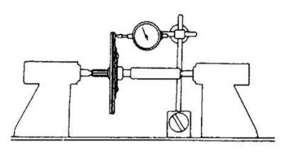
Fig. 3.18. Checking the axial runout of the disk
Using a dial indicator, check the axial runout of the disk (Fig. 3.18).
Maximum axial runout: 0.7 mm.
If the axial runout exceeds the established norms, replace the disc.
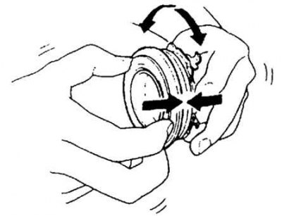
Fig. 3.19. Checking the release bearing
Applying axial pressure to the release bearing, turn it (Fig. 3.19).
If the bearing is binding or there is significant resistance to rotation, replace the bearing.
Note: Sealed bearing does not require flushing or lubrication.
Applying axial pressure to the primary shaft support bearing of the gearbox, turn it.
If the bearing is binding or there is significant resistance to rotation, replace the bearing.
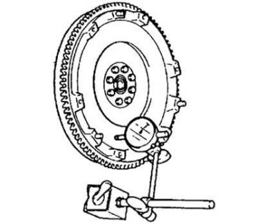
Fig. 3.20. Checking the flywheel axial runout
Using a dial indicator, check the axial runout of the flywheel (Fig. 3.20).
Maximum axial runout: 0.2 mm.
If the axial runout exceeds the established norms, replace the flywheel.
Installation
Install the flywheel onto the crankshaft.
If using old bolts, remove any remaining old sealant from the threaded flywheel mounting bolt holes in the crankshaft and from the flywheel mounting bolts. Apply sealant to the flywheel mounting bolts and install them.
The article is copied from the resource MazBook
Note: If you are installing a new bolt, do not apply sealant to it.
Tighten the flywheel mounting bolts by hand.
Secure the flywheel from turning using a special tool.
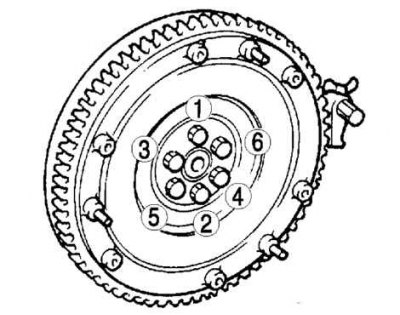
Fig. 3.21. Flywheel mounting bolt tightening sequence
Tighten the mounting bolts in two or three passes in the sequence shown in Figure 3.21.
Tightening torque: 108–115 Nm.
Using the special tool, install the new transmission input shaft support bearing.
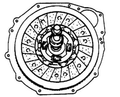
Fig. 3.22. Installing the driven clutch disc
Install the driven clutch disc and fix its position using the disc centering tool (3.22).
Install the clutch cover.
Install the special device.
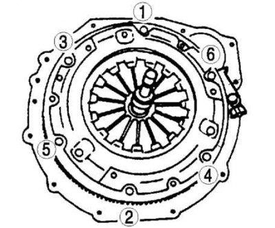
Fig. 3.23. The order of tightening the pressure plate mounting bolts
Tighten the pressure plate mounting bolts evenly and gradually in the sequence shown in the figure (Fig. 3.23).
Tightening torque: 18.6–25.5 Nm.
Install the clutch release fork support into the gearbox.
Install the clutch release bearing clamp onto the bearing.
Apply grease to the contact surfaces of the clutch release fork and sleeve, the fork and pushrod, and the fork support points.
Apply clutch spline grease to the drive shaft splines and clutch splines.
Install the clutch release fork with the clutch release bearing into the gearbox.
Note: After installation, move the fork forward and backward to check that the release bearing moves smoothly.
Install the clutch release fork boot.
Install the gearbox.