


Car steering Mazda 6 (GG)

General information about steering
Fig. 5.1. Steering mechanism of the Mazda 6: 1 – with left-hand steering; 2 – with right-hand steering; 3 – ATX; 4 – MTX; 5 – steering wheel; 6 – steering column and...
Fig. 5.1. Steering mechanism of the Mazda 6: 1 – with left-hand steering; 2 – with right-hand steering; 3 – ATX; 4 – MTX; 5 – steering wheel; 6 – steering column and...

Variable-rate steering (depending on engine speed)
The design and operation of the steering system is basically the same as the 626 (GF) except for the following. Mazda 6 vehicles use a variable-rate telescopic...
The design and operation of the steering system is basically the same as the 626 (GF) except for the following. Mazda 6 vehicles use a variable-rate telescopic...

Checking the power steering fluid
Checking the working fluid level Check the power steering fluid level. If necessary, top up the fluid level to normal. Power steering fluid ATF M III or equivalent (e.g....
Checking the working fluid level Check the power steering fluid level. If necessary, top up the fluid level to normal. Power steering fluid ATF M III or equivalent (e.g....

Checking the steering wheel free play
Set the wheels to the straight-ahead position and, by turning the steering wheel slightly left and right, check that the free play is within the norm. If the steering...
Set the wheels to the straight-ahead position and, by turning the steering wheel slightly left and right, check that the free play is within the norm. If the steering...

Checking the steering column
Fig. 5.8. Checking the steering column By moving the steering wheel as shown in Figure 5.8, check the wear of the steering column bearing, free play in the steering...
Fig. 5.8. Checking the steering column By moving the steering wheel as shown in Figure 5.8, check the wear of the steering column bearing, free play in the steering...

Checking the steering wheel effort
Check the following: tire size and tire pressure; fluid level in the power steering reservoir; tension of the power steering pump drive belt. Place the vehicle on a...
Check the following: tire size and tire pressure; fluid level in the power steering reservoir; tension of the power steering pump drive belt. Place the vehicle on a...
Precautions when working with the passive restraint system (SRS)
Warning! Improper handling of the airbag module may result in unexpected deployment of the airbag and injury to the worker. Be sure to read the safety instructions when...
Warning! Improper handling of the airbag module may result in unexpected deployment of the airbag and injury to the worker. Be sure to read the safety instructions when...

Removal, checking and installation the steering wheel and steering column
The steering gear has a rotary control valve that directs fluid from the power steering pump to one side or the other of the piston in the steering rack. The piston and...
The steering gear has a rotary control valve that directs fluid from the power steering pump to one side or the other of the piston in the steering rack. The piston and...

Disassembling the steering rod
Caution! When securing the steering gear bracket in a vice, place copper plates on the vice jaws and place a rag or similar material underneath. Fig. 5.16. Components of...
Caution! When securing the steering gear bracket in a vice, place copper plates on the vice jaws and place a rag or similar material underneath. Fig. 5.16. Components of...

Disassembling the gear shaft and housing
Fig. 5.20. Removing the housing Holding the pinion shaft as shown in Figure 5.20, remove the housing and pinion shaft. Note: If the pinion shaft cannot be removed by...
Fig. 5.20. Removing the housing Holding the pinion shaft as shown in Figure 5.20, remove the housing and pinion shaft. Note: If the pinion shaft cannot be removed by...

Disassembling the upper bearing and seal
Fig. 5.23. Removing the seal and upper bearing Install the special device as shown in Figure 5.23. Using a press, remove the seal and upper bearing without applying...
Fig. 5.23. Removing the seal and upper bearing Install the special device as shown in Figure 5.23. Using a press, remove the seal and upper bearing without applying...

Disassembling the inner guide seal
Install special tools on the valve side. Install the special device on the gear housing. Fig. 5.25. Pressing out the seal and inner guide Press out the seal and the...
Install special tools on the valve side. Install the special device on the gear housing. Fig. 5.25. Pressing out the seal and inner guide Press out the seal and the...

Checking the steering rack
Check the rack for cracks, damage and wear of the teeth. Replace the rack if necessary. Fig. 5.27. Measuring the rack runout Measure the rack runout (Fig. 5.27)....
Check the rack for cracks, damage and wear of the teeth. Replace the rack if necessary. Fig. 5.27. Measuring the rack runout Measure the rack runout (Fig. 5.27)....

Checking the tie rod end
Check the tie rod end for cracks and damage to the protective boot. Replace it if necessary. Check the ball joint clearance. Replace the tie rod end if necessary. Rotate...
Check the tie rod end for cracks and damage to the protective boot. Replace it if necessary. Check the ball joint clearance. Replace the tie rod end if necessary. Rotate...

Checking the steering rod
Check the steering rod for deformation and damage. Replace it if necessary. Check the ball joint clearance. Replace the steering rod if necessary. Rock the steering rod...
Check the steering rod for deformation and damage. Replace it if necessary. Check the ball joint clearance. Replace the steering rod if necessary. Rock the steering rod...

Removal and installation the power steering pump
Fig. 5.30. Power steering pump: 1 – drive belt; 2 – pressure sensor connector; 3 – pressure pipeline; 4 – suction hose; 5 – power steering pump Remove the drive belt....
Fig. 5.30. Power steering pump: 1 – drive belt; 2 – pressure sensor connector; 3 – pressure pipeline; 4 – suction hose; 5 – power steering pump Remove the drive belt....
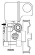
Assembly of power steering pump components
Fig. 5.34. Installing the power steering pump clamp Place the clamp in the direction shown in Figure 5.34. Make sure the clamp eye is locked in place. Fig. 5.35....
Fig. 5.34. Installing the power steering pump clamp Place the clamp in the direction shown in Figure 5.34. Make sure the clamp eye is locked in place. Fig. 5.35....
This section is available on: russian, bulgarian, belarusian, ukrainian, serbian, croatian, romanian, polish, slovak, hungarian
More sections on repairs of other Mazda models
• Chassis: Steering Mazda Familia 5 (1985-1989)
• Chassis: Steering Mazda Capella 3 and 4 (1982-1992)
• Chassis: Steering Mazda3 BK (2003-2009)
• Chassis: Steering Mazda CX-5KE (2012-2017)
• Chassis: Steering Mazda BT-50 (1) (2006-2011)
• Chassis: Steering Mazda Familia 5 (1985-1989)
• Chassis: Steering Mazda Capella 3 and 4 (1982-1992)
• Chassis: Steering Mazda3 BK (2003-2009)
• Chassis: Steering Mazda CX-5KE (2012-2017)
• Chassis: Steering Mazda BT-50 (1) (2006-2011)
Link in different formats to this section
TEXTHTMLBB Code
- User manual
- Vehicle description
- Keys, locks and alarms
- Controls and instruments
- Air conditioning and heater
- Seat adjustment
- Security systems
- Driving and operation
- Faults en route
- Maintenance
- Power unit
- Engine device
- Engine repair
- Lubrication system
- Cooling system
- Fuel system
- Exhaust system
- Electrical equipment of engines
- Control system
- Transmission
- Clutch
- Mechanical gearbox
- Automatic gearbox
- Drive shafts and hubs
- Chassis
- Suspension and wheels
- Steering
- Brake system
- Body
- Exterior (external elements)
- Interior (internal elements)
- Doors and windows
- Air conditioning and heater
- Electrical equipment
- Equipment and devices
- Power devices
- Lighting system
- Windshield wipers and washers