
Attention! When fixing the steering bracket in a vise, place copper plates on the jaws of the vise, place a rag or similar material on it.
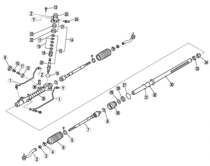
Pic. 5.16. Steering gear and tie rod components: 1 - hydraulic system pipeline; 2 – a tip of steering draft; 3 - locknut; 4 – a collar of a protective cover; 5 - tape collar of the protective cover; 6 - protective cover; 7 – steering draft; 8 - washer; 9 - locknut (adjusting cover); 10 - adjusting cover; 11 - rail stop spring; 12 - rail stop; 13 - bolt; 14 - gear shaft and housing; 15 - gear shaft; 16 - sealing ring; 17 - retaining ring; 18 - control valve; 19 - ring seal; 20 - gear shaft; 21 - valve body; 22 - upper bearing; 23 - stuffing box; 24 - return pipeline; 25 - valve body; 26 - holder; 27 - sealing ring; 28 - U-shaped gasket; 29 - support ring; 30 - steering rack; 31 - ring seal; 32 - sealing ring; 33 - stuffing box; 34 - inner guide; 35 – the case of the steering mechanism; 36 - rubber support
The components of the steering mechanism and steering rods are shown in fig. 5.16.
Remove the parts in the order shown in Figure 5.16.
Expand the puck.
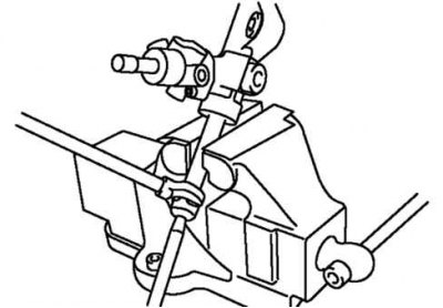
Pic. 5.17. Removing the tie rod
Remove the tie rod (pic. 5.17).
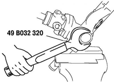
Pic. 5.18. Removing the locknut
Remove the locknut using the special tool (pic. 5.18).
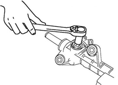
Pic. 5.19. Removing the adjustment cover
Remove the adjustment cover (pic. 5.19).