


This force is transmitted through the steering rods and steering rod ends to the steering knuckles, which turn the front wheels. If the power steering is faulty, the car is controlled normally. However, more force must be applied. The rotational motion of the steering wheel is transmitted to the pinion. When the pinion rotates, its teeth engage with the teeth of the rack, thereby causing the rack to move.
Removal
Caution! When removing the steering wheel, do not strike the shaft with a hammer. The steering column may become deformed.
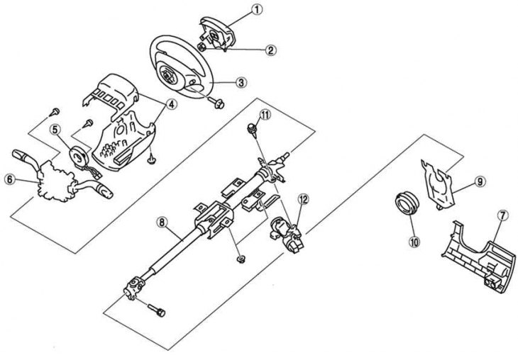
Fig. 5.10. Steering column components: 1 – airbag module; 2 – lock nut; 3 – steering wheel; 4 – steering column trim; 5 – spiral spring; 6 – combination switch; 7 – bottom panel; 8 – steering shaft; 9 – hinge cover; 10 – dust cover; 11 – Steering lock mechanism mounting bolts; 12 – steering lock mechanism part
Set the vehicle wheels to the straight-ahead position.
Remove the steering wheel using a suitable puller.
Using a chisel and hammer, make grooves in the heads of the steering lock mounting bolts.
Original material on the website [www.mazbook.ru]
Unscrew the bolts with a screwdriver.
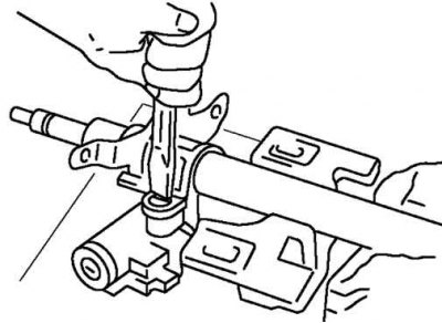
Fig. 5.11. Dismantling the steering lock mechanism part
Remove the steering lock mechanism part (Fig. 5.11).
Examination
Check the steering column bearing for damage.
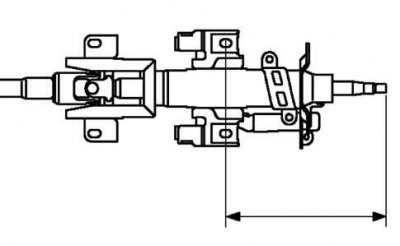
Fig. 5.12. Checking the length of the steering shaft
Check the length of the steering shaft (Fig. 5.12).
Replace the steering shaft if necessary.
Length: 211.6 mm.
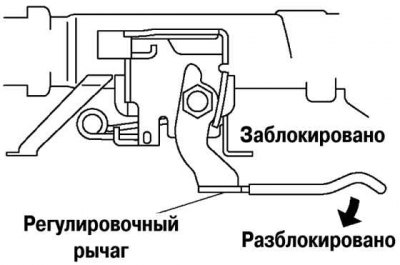
Fig. 5.13. Checking the operation of the tilt and longitudinal adjustment mechanisms of the steering column
Check the operation of the tilt and longitudinal adjustment mechanisms of the steering column (Fig. 5.13).
Make sure the lever moves smoothly from the unlocked position to the locked position.
Make sure that the steering shaft is securely locked when the lever is set to the "locked" position.
Replace the steering shaft if necessary.
Installation
Install the steering lock mechanism part onto the steering shaft.
Make sure the locking mechanism is working properly.
Install new locking mechanism mounting bolts.
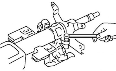
Fig. 5.14. Tightening the locking mechanism mounting bolts
Tighten the bolts until the heads break off (Fig. 5.14).
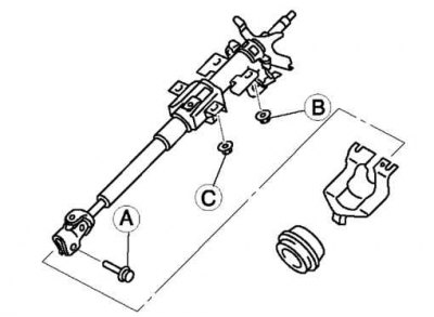
Fig. 5.15. Steering shaft mounting bolts
Lock the steering column tilt mechanism lever (Fig. 5.15).
- Tighten bolt A.
- Tighten nut B.
- Tighten nut C.
Caution! Do not strike in the direction of the shaft axis.
Set the car wheels to the straight-ahead position, set the steering wheel.