
Warning. The models described in this manual are equipped with an airbag system. Before working in close proximity to shock sensors, steering column or right panel, disconnect the cable from the negative battery terminal, then the cable from the positive battery terminal, then wait at least 3 minutes. Accidental airbag deployment can cause injury (see paragraph 28).
Examination
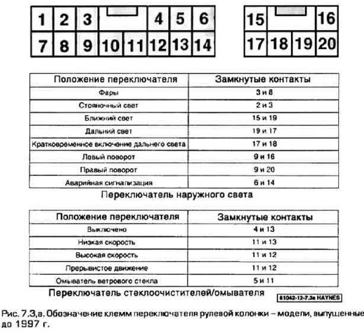
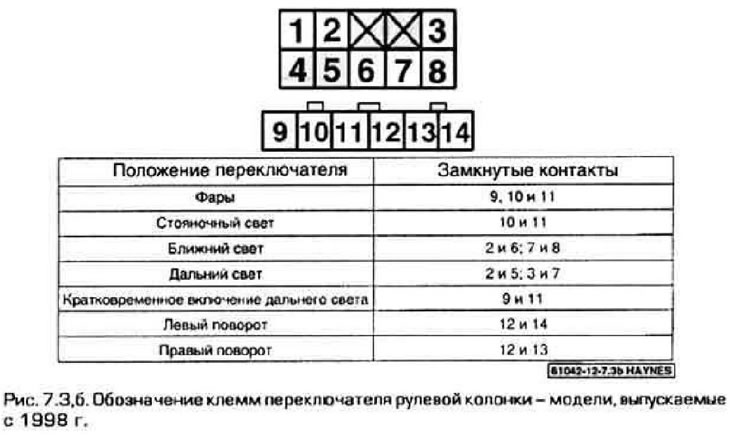
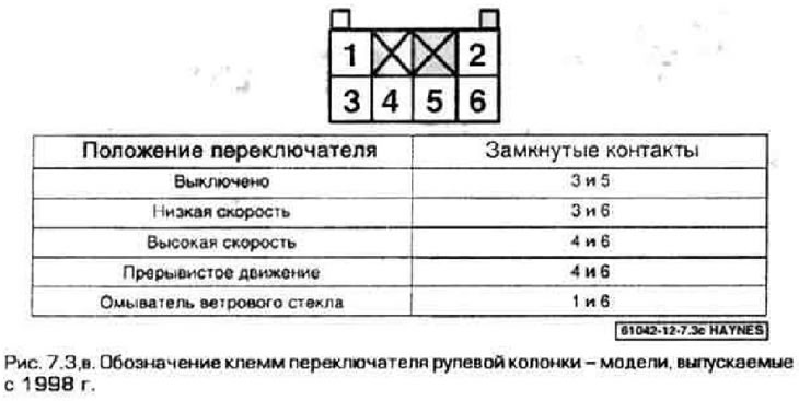
1. The multi-function switch is installed on the top of the steering column. The left switch turns on the direction indicator circuits, hazard warning lamps, and also switches the headlights. The right switch turns on the windshield wipers and washers. Models manufactured prior to 1997 have both switches combined into one unit. On 1993 and 1994 models, the airbag coil spring can be removed from the switch block. On 1995 and 1996 models, the coil spring is part of the switch block and can only be replaced with the switches. On models since 1998, the switches are made in two blocks and can be replaced separately from each other.
2. On pre-1997 models, remove the lower section of the steering column trim and disconnect the 6-pin and 12-pin connectors located at the base of the steering column. Further testing is carried out on these connectors. For models manufactured since 1998, remove each switch to be tested.
3. Using an ohmmeter or test lamp and the appropriate wiring diagram, check for contact between the switch terminals in each position (pic. 7.3, a-c). If there is no contact between the terminals, replace the switch.
Replacement
Models released before 1997
4. Disconnect the wire from the negative battery terminal.
Warning. Your car's radio is equipped with an anti-theft system. Please read the information at the beginning of this manual before disconnecting the battery.
5. Set the front wheels to the straight ahead position. Remove the steering wheel (see chapter 10). Remove the steering column trim and the lower section of the front panel trim (see chapter 11).
6. For 1993 to 1994 models, apply two strips of tape across the airbag coil spring and outer housing (for fixing springs). Remove the three screws securing the coil spring to the switch. Disconnect the electrical connector and ground wire, then remove the coil spring.
7. On 1995 to 1997 models, the coil spring is part of the derailleur, so DO NOT ATTEMPT to remove the coil spring from the derailleur. New derailleurs have the coil spring set to the middle position.
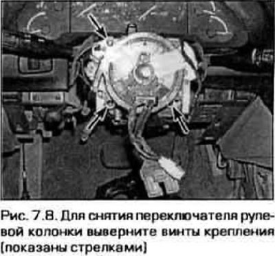
8. Turn out screws of fastening of the switch, disconnect sockets of electroconducting, then remove the switch from a steering column (pic. 7.8).
9. Installation is made in sequence, return to removal. If the coil spring was deployed before installation. set it to the middle position as follows:
- A) Turn the coil spring hub clockwise until it stops.
- 6) Turn the hub counterclockwise 2 and 3/4 turns and align the mark on the hub with the mark on the spring housing.
- V) Before setting the coil spring to the middle position, make sure that the front wheel of the vehicle is in the straight ahead position.
Models since 1998
10. Remove the steering column trim (see chapter 11).
11. Disconnect from the switch a socket of electroconducting.
12. Turn out screws of fastening and remove the switch from a steering column.
13. Installation is made in sequence, return to removal.