


Equipment and devices Mazda 626 (3 and 4)

General information about electrical equipment
Consumers are connected to the positive power source via a wire, and to the negative power source via the vehicle body (ground). This method reduces the number of wires...
Consumers are connected to the positive power source via a wire, and to the negative power source via the vehicle body (ground). This method reduces the number of wires...

Determining the source of the fault
An electrical circuit consists of an electrical component, switches, relays, motors, fuses, circuit breakers, wires, and connectors that connect the electrical component...
An electrical circuit consists of an electrical component, switches, relays, motors, fuses, circuit breakers, wires, and connectors that connect the electrical component...

Fuses and fuse links
Figure 13.2. Location of the fuse box under the instrument panel on the driver's side Fuses and fusible links are used to protect electrical circuits. The fuse box is...
Figure 13.2. Location of the fuse box under the instrument panel on the driver's side Fuses and fusible links are used to protect electrical circuits. The fuse box is...

Checking the three-way adjustable shock absorber drive
Remove the shock absorber drive cover and disconnect the connector. Figure 13.27. Location of contacts ("L", "B", "W") of the three-way adjustable shock absorber drive...
Remove the shock absorber drive cover and disconnect the connector. Figure 13.27. Location of contacts ("L", "B", "W") of the three-way adjustable shock absorber drive...
Combination switch — removal and installation
Disconnect the cable from the negative battery terminal. Remove the steering wheel. Remove the screws and remove the upper and lower steering column covers. Remove the...
Disconnect the cable from the negative battery terminal. Remove the steering wheel. Remove the screws and remove the upper and lower steering column covers. Remove the...
Ignition switch — removal and installation
To access the ignition switch, remove the steering wheel and combination switch. Drill out the ignition switch mounting bolts or loosen them by turning them with a...
To access the ignition switch, remove the steering wheel and combination switch. Drill out the ignition switch mounting bolts or loosen them by turning them with a...

Headlight with headlight bulb
Remove the radiator grille cover (if it is installed) and radiator grille. Disconnect the cable from the negative battery terminal. Loosen the screws and remove the...
Remove the radiator grille cover (if it is installed) and radiator grille. Disconnect the cable from the negative battery terminal. Loosen the screws and remove the...

Headlight with replaceable bulb
Figure 13.29. Fastening elements of a headlight with a replaceable bulb: 1 – headlight adjustment screw; 2 – bracket; 3 – lid; 4 – lamp and socket; 5 – inner spring; 6,...
Figure 13.29. Fastening elements of a headlight with a replaceable bulb: 1 – headlight adjustment screw; 2 – bracket; 3 – lid; 4 – lamp and socket; 5 – inner spring; 6,...

Headlight adjustment
It is very important that the direction of the headlight beam is adjusted correctly. Please note: Holts Amber Lamps are recommended for replacing headlights with those...
It is very important that the direction of the headlight beam is adjusted correctly. Please note: Holts Amber Lamps are recommended for replacing headlights with those...

Replacing lamps
Before replacing the exterior lighting bulb, disconnect the cable from the negative terminal of the battery. Be aware that if the lamp has just been lit, it may be too...
Before replacing the exterior lighting bulb, disconnect the cable from the negative terminal of the battery. Be aware that if the lamp has just been lit, it may be too...

Removal and installation the radio
Figure 13.37. Location of the radio, speakers and wires in the car: a – for cars with sedan and coupe bodies; b – for hatchback vehicles; 1 – antenna installed in the...
Figure 13.37. Location of the radio, speakers and wires in the car: a – for cars with sedan and coupe bodies; b – for hatchback vehicles; 1 – antenna installed in the...
Removal and installation speakers
The rear speakers can be removed after opening the trunk. To access the front speakers, you need to remove the speaker cover. Remove the screws, pull the speaker out of...
The rear speakers can be removed after opening the trunk. To access the front speakers, you need to remove the speaker cover. Remove the screws, pull the speaker out of...

Antenna with amplifier — removal and installation
Figure 13.38. Main elements and location of the antenna with amplifier on the vehicle: 1 – antenna amplifier; 2 – antenna mast; 3 – antenna drive motor; 4 – antenna...
Figure 13.38. Main elements and location of the antenna with amplifier on the vehicle: 1 – antenna amplifier; 2 – antenna mast; 3 – antenna drive motor; 4 – antenna...

Instrument cluster — removal and installation
Removal and installation Disconnect the negative battery cable and lower the adjustable steering column. Figure 13.42. Instrument cluster mounting elements with...
Removal and installation Disconnect the negative battery cable and lower the adjustable steering column. Figure 13.42. Instrument cluster mounting elements with...

Instrument panel switches
Disconnect the cable from the negative battery terminal. Switch blocks Remove the instrument cluster. Figure 13.46. Fastening elements of the right switch block: 1 –...
Disconnect the cable from the negative battery terminal. Switch blocks Remove the instrument cluster. Figure 13.46. Fastening elements of the right switch block: 1 –...

Heater control panel
Disconnect the cable from the negative battery terminal. Use a screwdriver to pry the air conditioner switch away from the rotary ventilation grille assembly and...
Disconnect the cable from the negative battery terminal. Use a screwdriver to pry the air conditioner switch away from the rotary ventilation grille assembly and...

Heater control cables
Air flow distribution control cable Figure 13.50. Adjusting the air flow distribution cable: 1 – heated glass; 2 – cabin ventilation; 3 – stroke size Set the control...
Air flow distribution control cable Figure 13.50. Adjusting the air flow distribution cable: 1 – heated glass; 2 – cabin ventilation; 3 – stroke size Set the control...

Windscreen wipers and washers — removal and installation
Windshield wiper Disconnect the cable from the negative battery terminal. Figure 13.53. Windshield wiper: 1 – windshield wiper blade; 2 – nut and wiper arm; 3 – lid; 4 –...
Windshield wiper Disconnect the cable from the negative battery terminal. Figure 13.53. Windshield wiper: 1 – windshield wiper blade; 2 – nut and wiper arm; 3 – lid; 4 –...
Rear window defroster
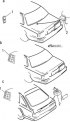
Figure 13.57. Rear window defroster elements: a – sedan body; b – coupe body; c – hatchback body; 1 – heater switch; 2 – interference suppression element The rear window...
Figure 13.57. Rear window defroster elements: a – sedan body; b – coupe body; c – hatchback body; 1 – heater switch; 2 – interference suppression element The rear window...
Sound alarm system
The sound alarms warn the driver of various faults and control errors by means of four different sound signals. The following signals correspond to the systems and...
The sound alarms warn the driver of various faults and control errors by means of four different sound signals. The following signals correspond to the systems and...

Constant speed control system (cruise control)
Figure 13.58. Location of the main elements of the constant speed control system (cruise control): a – models with a switch block; b – models without switch block; 1 –...
Figure 13.58. Location of the main elements of the constant speed control system (cruise control): a – models with a switch block; b – models without switch block; 1 –...

Removal and installation the turn signal flasher
A standard flasher is used to operate the turn signals and hazard warning lights and is located on the bracket to the left of the steering column. Disconnect the cable...
A standard flasher is used to operate the turn signals and hazard warning lights and is located on the bracket to the left of the steering column. Disconnect the cable...
Checking the fuel level and coolant temperature sensors
If the fuel level and coolant temperature gauges are giving incorrect readings, the gauge, sensor, or wiring may be faulty. The fault can be identified using a...
If the fuel level and coolant temperature gauges are giving incorrect readings, the gauge, sensor, or wiring may be faulty. The fault can be identified using a...

Fuel level indicator
The fuel level sensor can be accessed after removing the rear seat and cover. Disconnect the connector from the fuel level sensor. Figure 13.61. Connecting a resistor...
The fuel level sensor can be accessed after removing the rear seat and cover. Disconnect the connector from the fuel level sensor. Figure 13.61. Connecting a resistor...

Fuel level sensor
Figure 13.64. Removing the fuel level sensor mounting screws Remove the screws and the fuel level sensor (figure 13.64). Figure 13.65. Fuel level sensor resistance...
Figure 13.64. Removing the fuel level sensor mounting screws Remove the screws and the fuel level sensor (figure 13.64). Figure 13.65. Fuel level sensor resistance...

Coolant temperature gauge
Disconnect the connector from the temperature sensor located at the rear of the thermostat housing. Connect a resistor with a resistance of 12 to 230 ohms between the...
Disconnect the connector from the temperature sensor located at the rear of the thermostat housing. Connect a resistor with a resistance of 12 to 230 ohms between the...
Coolant temperature sensor
Drain the coolant to a level below the sensor and unscrew it. Hang the sensor on a thread in a glass container filled with water and connect the ohmmeter probes to the...
Drain the coolant to a level below the sensor and unscrew it. Hang the sensor on a thread in a glass container filled with water and connect the ohmmeter probes to the...

Replacing the relay
Figure 13.69. Location of the relay in the car: 1 – headlight relay; 2 – ignition relay; 3 – radiator fan relay; 4 – central locking relay; 5 – sound signal relay; 6 –...
Figure 13.69. Location of the relay in the car: 1 – headlight relay; 2 – ignition relay; 3 – radiator fan relay; 4 – central locking relay; 5 – sound signal relay; 6 –...

Lock illumination system
On vehicles equipped with a door lock illumination system, the driver's door lock and ignition switch are illuminated for approximately 20 seconds after the door handle...
On vehicles equipped with a door lock illumination system, the driver's door lock and ignition switch are illuminated for approximately 20 seconds after the door handle...
Checking the central relay (since 1984)
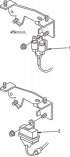
Figure 14.22. Central relay of the old (1) and new (2) types The central relay is located on the left side of the engine compartment and is secured with a nut to the...
Figure 14.22. Central relay of the old (1) and new (2) types The central relay is located on the left side of the engine compartment and is secured with a nut to the...

Fuse box (since 1984)
Figure 14.39. Main fuse box mounting elements In addition to the fuse box located under the instrument panel on the driver's side, the main fuse box is located on the...
Figure 14.39. Main fuse box mounting elements In addition to the fuse box located under the instrument panel on the driver's side, the main fuse box is located on the...

Headlights — removal and installation (since 1984)
Figure 14.40. Headlight of later model cars: 1 – radiator trim; 2 – spring; 3 – direction indicator lens and lamp; 4 – headlight On later production cars, the twin...
Figure 14.40. Headlight of later model cars: 1 – radiator trim; 2 – spring; 3 – direction indicator lens and lamp; 4 – headlight On later production cars, the twin...

Radio receiver — removal and installation (since 1984)
To disconnect the side clamps of the radio from the walls of the socket, you need to use two key plates. Disconnect the cable from the negative battery terminal. Figure...
To disconnect the side clamps of the radio from the walls of the socket, you need to use two key plates. Disconnect the cable from the negative battery terminal. Figure...

Instrument cluster — removal and installation (since 1984)
Removal and installation the instrument cluster Disconnect the cable from the negative battery terminal. Lower the steering column or remove the steering wheel. Remove...
Removal and installation the instrument cluster Disconnect the cable from the negative battery terminal. Lower the steering column or remove the steering wheel. Remove...
Instrument cluster switches (since 1984)
Disconnect the cable from the negative battery terminal. Lower the steering column or remove the steering wheel. Loosen the screws securing the instrument cluster trim...
Disconnect the cable from the negative battery terminal. Lower the steering column or remove the steering wheel. Loosen the screws securing the instrument cluster trim...
Map reading lamp replacement (since 1984)
Disconnect the cable from the negative battery terminal. Remove the cover from the lamp housing. Move the rearview mirror all the way back and down to remove it from the...
Disconnect the cable from the negative battery terminal. Remove the cover from the lamp housing. Move the rearview mirror all the way back and down to remove it from the...
Digital watches (since 1984)
Remove the instrument cluster trim panel. Remove the screws, remove the watch and disconnect the connectors. Installation is carried out in the reverse order of removal.
Remove the instrument cluster trim panel. Remove the screws, remove the watch and disconnect the connectors. Installation is carried out in the reverse order of removal.

Location of relays in a car (since 1984)
Installation is carried out in the reverse order of removal. Figure 14.45. Location of relays on vehicles with the RVT system: 1 – timer; 2 – direction indicator switch;...
Installation is carried out in the reverse order of removal. Figure 14.45. Location of relays on vehicles with the RVT system: 1 – timer; 2 – direction indicator switch;...
This section is available on: russian, bulgarian, belarusian, ukrainian, serbian, croatian, romanian, polish, slovak, hungarian
More sections on repairs of other Mazda models
• Electrical equipment: Equipment and devices Mazda Familia 5 (1985-1989)
• Electrical equipment: Equipment and devices Mazda3 BK (2003-2009)
• Electrical equipment: Equipment and devices Mazda6 GG (2002-2008)
• Electrical equipment: Equipment and devices Mazda CX-5KE (2012-2017)
• Electrical equipment: Equipment and devices Mazda BT-50 (1) (2006-2011)
• Electrical equipment: Equipment and devices Mazda Familia 5 (1985-1989)
• Electrical equipment: Equipment and devices Mazda3 BK (2003-2009)
• Electrical equipment: Equipment and devices Mazda6 GG (2002-2008)
• Electrical equipment: Equipment and devices Mazda CX-5KE (2012-2017)
• Electrical equipment: Equipment and devices Mazda BT-50 (1) (2006-2011)
Link in different formats to this section
TEXTHTMLBB Code
- General information
- Introduction to guide
- User manual
- Troubleshooting
- Maintenance
- Power unit
- 4-cylinder engines
- 6-cylinder engines
- Engine overhaul
- Cooling and ventilation
- Power and exhaust systems
- Engine electrics
- Control system
- Transmission
- Mechanical gearbox
- Automatic gearbox
- Clutch and drive shafts
- Chassis
- Brake system
- Car suspension
- Steering
- Body
- Exterior (external elements)
- Interior (internal elements)
- Doors, windows and locks
- Electrical equipment
- Equipment and devices
- Electrical circuits
- General information
- User manual
- Maintenance
- Helpful hints
- Power unit
- Petrol engines 1.6 and 1.8
- Petrol engines 2.0
- 2.5 petrol engines
- Overhaul engines 1.6 and 1.8
- Overhaul engines 2.0 and 2.5
- Diesel engine 2.0
- Engine electrics
- Cooling system
- Air conditioner
- Carburetor Nikki 30/34
- Power system (1.6 and 1.8)
- Power system (2.0 and 2.5)
- Control system
- Transmission
- Mechanical gearbox
- Automatic gearbox
- Clutch and axles
- Chassis
- Brake system
- Suspension and wheels
- Steering
- Body
- Exterior (external elements)
- Interior (internal elements)
- Doors and windows
- Electrical equipment
- Equipment and devices
- Electrical circuits
- General information
- Introduction to manual
- Vehicle specifications
- Power unit
- Engine repair
- Lubrication system
- Cooling system
- Fuel system (carburetor)
- Fuel injection (FE)
- Fuel injection (DOHC)
- Fuel system (diesel)
- Ignition system
- Transmission
- Clutch
- Gearbox
- Drive shafts
- Chassis
- Front suspension
- Rear suspension
- Steering system
- Brake system
- Electrical equipment
- Equipment and devices
- Electrical circuits
- General information
- User manual
- Maintenance
- Power unit
- Gasoline engine
- Engine overhaul (gasoline)
- Diesel engine
- Cooling and heating
- Supply system
- Ignition system
- Emission reduction
- Transmission
- Clutch
- Mechanical gearbox
- Automatic gearbox
- Drive shafts
- Chassis
- Brake system
- Suspension and wheels
- Steering
- Body
- Exterior (external elements)
- Interior (internal elements)
- Electrical equipment
- Equipment and devices
- Power devices
- Electrical circuits
- General information
- User manual
- Maintenance
- Troubleshooting
- Late models
- Power unit
- Engine in car
- Engine overhaul
- Cooling and heating system
- Fuel and exhaust system
- Engine electrical system
- Emission control system
- Transmission
- Mechanical gearbox
- Automatic gearbox
- Clutch and drive shafts
- Chassis
- Brake system
- Suspension and wheels
- Steering
- Body
- Exterior (external elements)
- Interior (internal elements)
- Electrical equipment
- Equipment and devices
- Lighting and lamps
- Electrical circuits