MazBook.ru
English Русский
Български
Беларускі
Український
Српски
Hrvatski
Română
Polski
Slovenský
Magyar
• Bookmark • Sitemap • Contacts •   
Cars Opel Cars Ford Cars Volkswagen Cars Audi Cars Kia Cars Renault Cars Peugeot


Familia Capella Mazda3 Mazda6 CX-? Others Articles
Capella 3 (1982-1992, petrol) Capella 3 and 4 (1982-1992) Capella 4 (1987-1992) Capella 5 (1991-1997) Capella 6 (1997-2005, petrol)

Instrument cluster — removal and installation (Mazda Capella GC)

  • Home
  • Mazda Capella
  • Capella GC (1982-1992)
  • Electrical equipment
  • Equipment and devices
  • Instrument cluster — removal and installation
0
Contents: Removal and installation ⇓ Signposts ⇓

Removal and installation


Disconnect the negative battery cable and lower the adjustable steering column.

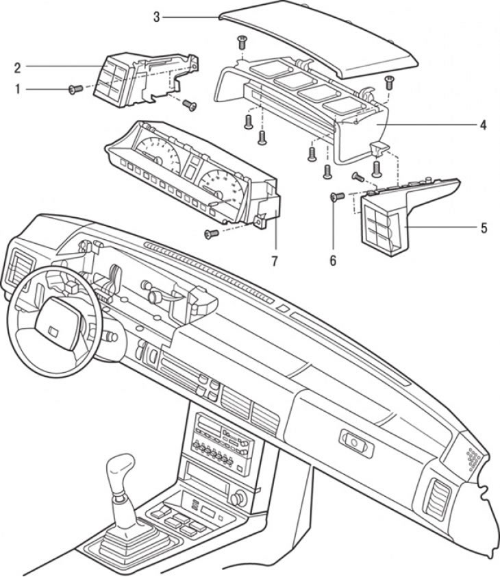
Figure 13.42. Instrument cluster mounting elements with switches: 1 – screws for fastening…

Figure 13.42. Instrument cluster mounting elements with switches: 1 – screws for fastening switches; 2 – left switch block; 3 – upper casing; 4 – instrument cluster trim; 5 – right switch block; 6 – screws for fastening switches; 7 – instrument cluster


Remove the screws securing the upper casing and instrument cluster trim (figure 13.42, 13.43).

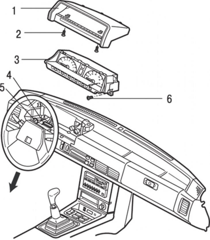
Figure 13.43. Instrument cluster mounting elements without switches: 1 – instrument cluster trim; 2…

Figure 13.43. Instrument cluster mounting elements without switches: 1 – instrument cluster trim; 2 – screw; 3 – instrument cluster; 4 – connectors; 5 – backlight lamp; 6 – instrument cluster mounting screw


Remove the instrument cluster mounting screws.

Disconnect the speedometer drive cable.

Pull out the instrument cluster, disconnect the connectors and remove the instrument cluster and switch blocks from the instrument panel.

Installation is carried out in the reverse order of removal.

Signposts


Disconnect the cable from the negative battery terminal.

Remove the instrument cluster.

Analog instrument cluster


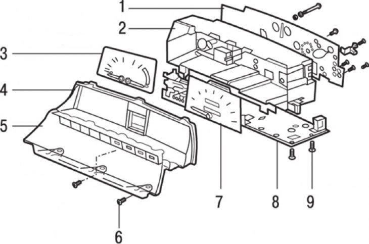
Figure 13.44. Analog instrument cluster: 1 – back plate; 2 – instrument cluster housing; 3 –…

Figure 13.44. Analog instrument cluster: 1 – back plate; 2 – instrument cluster housing; 3 – coolant temperature and fuel level indicators; 4 – frame; 5 – glass; 6 – glass fastening screw; 7 – speedometer; 8 – printed circuit board; 9 – PCB mounting screw


Remove the screws and remove the glass, circuit board and plate (figure 13.44).

Remove the bolts and remove the instrument cluster from the housing.

Installation is carried out in the reverse order of removal.

Digital instrument cluster


Remove the lamps, sockets and screws to release the printed circuit boards from the case.

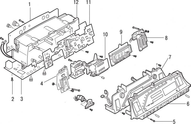
Figure 13.45. Elements of the electronic instrument cluster: 1 – back plate; 2 – screw for…

Figure 13.45. Elements of the electronic instrument cluster: 1 – back plate; 2 – screw for fastening the lower printed circuit board; 3 – lower printed circuit board; 4 – fuel level sensor; 5 – glass fastening screws; 6 – glass; 7 – tachometer and plate; 8 – coolant temperature sensor; 9 – speedometer; 10 – mileage counter; 11 – printed circuit board; 12 – instrument cluster housing


Remove the screws and remove the glass (figure 13.45).

Remove the tachometer and printed circuit board.

Remove the display switch.

Remove the lighting control unit and handle.

Remove the screws and disconnect the connectors from the speedometer, fuel gauge and coolant temperature gauge.

Installation is carried out in the reverse order of removal.

Replacing the speedometer drive cable


Remove the bolt and remove the speedometer cable and drive from the gearbox.

Partially pull out the instrument cluster to access the rear of the instrument cluster. Disconnect the cable from the speedometer.

Disconnect the cable from the firewall and remove it from the engine compartment.

Transfer all O-rings and, if necessary, the driven gear from the old cable to the new one.

Installation is carried out in the reverse order of removal. When installing, do not allow the new speedometer drive cable to form loops or pass it through narrow bushings.
This article is available at: russian, bulgarian, belarusian, ukrainian, serbian, croatian, romanian, polish, slovak, hungarian
This text was checked by: Georgy Afanasyev
Share with friends on social networks:

Previous
Capella 3 and 4 » Equipment and devices
Next

Antenna with amplifier — removal and installation
Removal and installation speakers
Removal and installation the radio
Replacing lamps
Headlight adjustment
Instrument panel switches
Heater control panel
Heater control cables
Windscreen wipers and washers — removal and installation
Rear window defroster
More articles on repairing other Mazda models
Instrument cluster details Mazda Familia 5 (1985-1989)
Instrument cluster Mazda3 BK (2003-2009)
Instrument cluster Mazda6 GG (2002-2008)
Instrument cluster Mazda CX-5KE (2012-2017)
Instrument cluster instruments, gauges and indicators Mazda BT-50 (1) (2006-2011)
Link in different formats to this article
Comments and feedback from visitors
No comments yet


How much will 29 + 21 ?


Capella 6 (1997-2005, petrol) 
  • General information
  • Introduction to guide
  • User manual
  • Troubleshooting
  • Maintenance
  • Power unit
  • 4-cylinder engines
  • 6-cylinder engines
  • Engine overhaul
  • Cooling and ventilation
  • Power and exhaust systems
  • Engine electrics
  • Control system
  • Transmission
  • Mechanical gearbox
  • Automatic gearbox
  • Clutch and drive shafts
  • Chassis
  • Brake system
  • Car suspension
  • Steering
  • Body
  • Exterior (external elements)
  • Interior (internal elements)
  • Doors, windows and locks
  • Electrical equipment
  • Equipment and devices
  • Electrical circuits
Capella 5 (1991-1997) 
  • General information
  • User manual
  • Maintenance
  • Helpful hints
  • Power unit
  • Petrol engines 1.6 and 1.8
  • Petrol engines 2.0
  • 2.5 petrol engines
  • Overhaul engines 1.6 and 1.8
  • Overhaul engines 2.0 and 2.5
  • Diesel engine 2.0
  • Engine electrics
  • Cooling system
  • Air conditioner
  • Carburetor Nikki 30/34
  • Power system (1.6 and 1.8)
  • Power system (2.0 and 2.5)
  • Control system
  • Transmission
  • Mechanical gearbox
  • Automatic gearbox
  • Clutch and axles
  • Chassis
  • Brake system
  • Suspension and wheels
  • Steering
  • Body
  • Exterior (external elements)
  • Interior (internal elements)
  • Doors and windows
  • Electrical equipment
  • Equipment and devices
  • Electrical circuits
Capella 4 (1987-1992) 
  • General information
  • Introduction to manual
  • Vehicle specifications
  • Power unit
  • Engine repair
  • Lubrication system
  • Cooling system
  • Fuel system (carburetor)
  • Fuel injection (FE)
  • Fuel injection (DOHC)
  • Fuel system (diesel)
  • Ignition system
  • Transmission
  • Clutch
  • Gearbox
  • Drive shafts
  • Chassis
  • Front suspension
  • Rear suspension
  • Steering system
  • Brake system
  • Electrical equipment
  • Equipment and devices
  • Electrical circuits
Capella 3 and 4 (1982-1992) 
  • General information
  • User manual
  • Maintenance
  • Power unit
  • Gasoline engine
  • Engine overhaul (gasoline)
  • Diesel engine
  • Cooling and heating
  • Supply system
  • Ignition system
  • Emission reduction
  • Transmission
  • Clutch
  • Mechanical gearbox
  • Automatic gearbox
  • Drive shafts
  • Chassis
  • Brake system
  • Suspension and wheels
  • Steering
  • Body
  • Exterior (external elements)
  • Interior (internal elements)
  • Electrical equipment
  • Equipment and devices
  • Power devices
  • Electrical circuits
Capella 3 (1982-1992, petrol) 
  • General information
  • User manual
  • Maintenance
  • Troubleshooting
  • Late models
  • Power unit
  • Engine in car
  • Engine overhaul
  • Cooling and heating system
  • Fuel and exhaust system
  • Engine electrical system
  • Emission control system
  • Transmission
  • Mechanical gearbox
  • Automatic gearbox
  • Clutch and drive shafts
  • Chassis
  • Brake system
  • Suspension and wheels
  • Steering
  • Body
  • Exterior (external elements)
  • Interior (internal elements)
  • Electrical equipment
  • Equipment and devices
  • Lighting and lamps
  • Electrical circuits
MazBook.ru © 2018–2026 · Mobile version · Articles and news · Sitemap: EN BG BY UA RS HR RO PL SK HU · Feedback · Site search · Add to bookmarks Familia 5 (BF) · Familia 6 (BG) · Capella 3 (GC) · Capella 3 and 4 (GC) · Capella 4 (GD) · Capella 5 (GE) · Capella 6 (GF) · Mazda3 BK · Mazda6 GG · CX-5KE · Mazda 121 (3) · Mazda BT-50 (1) ·
By continuing to use the site, you agree to the use of cookies 🔐