


Late model information Mazda 626 (3rd and 4th gen)

Late model specifications
The specifications below are revisions or additions to the preceding Sections Adjustment and Routine Maintenance Total by engine (all models) Engine idle speed: 1.6...
The specifications below are revisions or additions to the preceding Sections Adjustment and Routine Maintenance Total by engine (all models) Engine idle speed: 1.6...

Adjustment and routine maintenance of later models
Every 10,000 km or every 6 months, whichever comes first Check and adjust (if necessary) idle speed and mixture (EGI engine) Check and adjust (if necessary) ignition...
Every 10,000 km or every 6 months, whichever comes first Check and adjust (if necessary) idle speed and mixture (EGI engine) Check and adjust (if necessary) ignition...

Late model engine
Drive covers (late models) 1. Since May 1986, the engine drive covers have been changed as shown in the figure. The removal and installation procedures remain the same....
Drive covers (late models) 1. Since May 1986, the engine drive covers have been changed as shown in the figure. The removal and installation procedures remain the same....
Carburetor (late models) — description
1. The carburetor on later 2.0-liter models is equipped with an automatic choke, instead of the manual choke on earlier models. It incorporates a bimetallic spring that...
1. The carburetor on later 2.0-liter models is equipped with an automatic choke, instead of the manual choke on earlier models. It incorporates a bimetallic spring that...

Automatic air choke cover — removal and installation
1. With the air filter removed, disconnect the wire securing the automatic air damper. 2. Remove the screws and take out the cover, pressing the bimetallic spring away...
1. With the air filter removed, disconnect the wire securing the automatic air damper. 2. Remove the screws and take out the cover, pressing the bimetallic spring away...

Automatic air damper — checking and adjustment
1. The automatic air damper heater winding can be tested for continuity by disconnecting the supply wire and connecting an ohmmeter between the wire and ground. If the...
1. The automatic air damper heater winding can be tested for continuity by disconnecting the supply wire and connecting an ohmmeter between the wire and ground. If the...

Electronic Gas Injection (EGI) — description
1. The EGJ system is actually a Bosch L-Jctronic fuel injection system, manufactured under license from Mazda. The main components of the system are shown in the figures...
1. The EGJ system is actually a Bosch L-Jctronic fuel injection system, manufactured under license from Mazda. The main components of the system are shown in the figures...

Air Flow Meter (EGI) — check
1. Unscrew the clamp bar and remove the rubber boot from the wiring connector on the air flow meter (photo). Air flow meter wire connector clamp bar 2. Turn the ignition...
1. Unscrew the clamp bar and remove the rubber boot from the wiring connector on the air flow meter (photo). Air flow meter wire connector clamp bar 2. Turn the ignition...

Air Flow Meter (EGI) — removal and installation
1. Unscrew the clamping bar and remove the electrical connector from the air flow meter (photo). Removing the air flow meter wiring connector 2. Loosen the clamps and...
1. Unscrew the clamping bar and remove the electrical connector from the air flow meter (photo). Removing the air flow meter wiring connector 2. Loosen the clamps and...

Throttle Body (EGI) — inspection
1. Turn the throttle lever all the way and check that it moves freely. When at rest, the lever should come into contact with the stop adjustment screw. If necessary,...
1. Turn the throttle lever all the way and check that it moves freely. When at rest, the lever should come into contact with the stop adjustment screw. If necessary,...

Throttle body (EG/) — removal and installation
1. Drain the cooling system ( Section 1 ). 2. Loosen the clamp and disconnect the air intake pipe (photo). Air flow inlet duct (marked with an arrow) 3. Disconnect the...
1. Drain the cooling system ( Section 1 ). 2. Loosen the clamp and disconnect the air intake pipe (photo). Air flow inlet duct (marked with an arrow) 3. Disconnect the...

Throttle Position Sensor (EGI) — checking and adjusting
1. Pull the rubber boot off the wiring connector on the sensor located on the throttle body. 2. Turn on the ignition and, using a voltmeter with probes, check the...
1. Pull the rubber boot off the wiring connector on the sensor located on the throttle body. 2. Turn on the ignition and, using a voltmeter with probes, check the...
Pneumatic valve (EG/) — check
1. Start the engine at idle speed, then move the bypass air duct closer to the throttle body and check that the engine slows down. 2. If the engine is cold and does not...
1. Start the engine at idle speed, then move the bypass air duct closer to the throttle body and check that the engine slows down. 2. If the engine is cold and does not...

Accelerator cable (EGI) — adjustment
1. With the accelerator pedal fully released, check for 1.0-3.0 mm of free play on the inner cable or pedal, or in the throttle body. If necessary, loosen the locknuts...
1. With the accelerator pedal fully released, check for 1.0-3.0 mm of free play on the inner cable or pedal, or in the throttle body. If necessary, loosen the locknuts...

Fuel Injectors (EGI) — checking, removing and installing
1. Start the engine and warm it up to normal temperature, then set it to normal idle mode. 2. To quickly check the serviceability of the injector, place the tip of a...
1. Start the engine and warm it up to normal temperature, then set it to normal idle mode. 2. To quickly check the serviceability of the injector, place the tip of a...

Fuel Pressure (EGI) — check
1. For this test you will need a pressure gauge, along with a suitable T-connector and hose. 2. Disconnect the negative battery cable. 3. Disconnect the fuel supply hose...
1. For this test you will need a pressure gauge, along with a suitable T-connector and hose. 2. Disconnect the negative battery cable. 3. Disconnect the fuel supply hose...

Fuel Pump (EGI) — checking, removing and installing
1. To check the fuel pump pressure, follow the procedures given in the article "Fuel Pressure (EGI) - Checking", but without using the T-connector. Check that the fuel...
1. To check the fuel pump pressure, follow the procedures given in the article "Fuel Pressure (EGI) - Checking", but without using the T-connector. Check that the fuel...

Open Circuit Relay (EGI) — test
Open Circuit Relay Wiring Diagram 1. Open circuit relay (on the right side of the partition) supplies current to the fuel pump and pneumatic valve only when the engine...
Open Circuit Relay Wiring Diagram 1. Open circuit relay (on the right side of the partition) supplies current to the fuel pump and pneumatic valve only when the engine...
EGI Control System — check
1. The following components are related to the EGI control unit input circuits, and therefore any damage existing in the components will result in an inaccurate signal...
1. The following components are related to the EGI control unit input circuits, and therefore any damage existing in the components will result in an inaccurate signal...

Water Temperature Sensor (EGI) — checking, removing, and installing
Checking the EGI water temperature sensor 1. Remove the rubber boot from the wiring connector on the water temperature sensor (photo). EGI water temperature sensor...
Checking the EGI water temperature sensor 1. Remove the rubber boot from the wiring connector on the water temperature sensor (photo). EGI water temperature sensor...

Main Relay (EGI) — check
Early (A) and late (B) main relay 1. The main relay is located on the left side of the engine compartment (photo). Removing the EGI main relay 2. With the ignition on...
Early (A) and late (B) main relay 1. The main relay is located on the left side of the engine compartment (photo). Removing the EGI main relay 2. With the ignition on...

Air Conditioner Idle Control Valve (EGI) — adjustment
1. Start the engine and warm it up to normal temperature. 2. Stop the engine and connect the tachometer. 3. Disconnect the wiring connectors from the cooling fan motor...
1. Start the engine and warm it up to normal temperature. 2. Stop the engine and connect the tachometer. 3. Disconnect the wiring connectors from the cooling fan motor...

Power Steering Idle (EGI) Valve — adjustment
1. Connect the tachometer to the engine, then start the engine and warm it up to normal temperature. 2. Disconnect the electrical wiring connector from the valve. 3....
1. Connect the tachometer to the engine, then start the engine and warm it up to normal temperature. 2. Disconnect the electrical wiring connector from the valve. 3....

Electric Idle Governor (EGI) Valve — adjustment
1. Connect the tachometer to the engine, then start the engine and warm it up to normal temperature. 2. Separate the electrical wiring from the valve. 3. Connect the...
1. Connect the tachometer to the engine, then start the engine and warm it up to normal temperature. 2. Separate the electrical wiring from the valve. 3. Connect the...
Distributor — removal and repair
1. Since April 1985, a shock absorber has been installed on the centrifuge mechanism distributor to reduce noise. In all other respects, the distributor is identical to...
1. Since April 1985, a shock absorber has been installed on the centrifuge mechanism distributor to reduce noise. In all other respects, the distributor is identical to...

Fuel Economy Indicator (EGI) system
1. The details of the economy mode indication system on the EG1 engine are shown in the figure. The indicator is provided by two warning lights, one is an upshift...
1. The details of the economy mode indication system on the EG1 engine are shown in the figure. The indicator is provided by two warning lights, one is an upshift...

Air Intake System (EGI) — description
1. The air intake system fitted to EGI engines is shown in the figure and comprises two vacuum activated air control valves, a solenoid valve activated by the EGI...
1. The air intake system fitted to EGI engines is shown in the figure and comprises two vacuum activated air control valves, a solenoid valve activated by the EGI...

EGR Valve (EGI) — removal, inspection and installation
1. Unscrew the mounting plate, disconnect the vacuum hoses and remove the valves from the air cleaner extension. 2. A vacuum pump is needed to check the valve. Attach...
1. Unscrew the mounting plate, disconnect the vacuum hoses and remove the valves from the air cleaner extension. 2. A vacuum pump is needed to check the valve. Attach...

Thin Valves (EGI) — inspection, removal and installation
1. Start the engine and warm it up to normal temperature. 2. Remove the air control valves as described above. 3. Start the engine, then increase and decrease the engine...
1. Start the engine and warm it up to normal temperature. 2. Remove the air control valves as described above. 3. Start the engine, then increase and decrease the engine...

Air Injector Nozzles (EGI) — removal and installation
1. Unscrew the union nuts and remove the two secondary air ducts, placing them on one side (photo). EGI Air Injector Nozzle Parts Air ducts and injection tips assemblies...
1. Unscrew the union nuts and remove the two secondary air ducts, placing them on one side (photo). EGI Air Injector Nozzle Parts Air ducts and injection tips assemblies...

T-piece Solenoid Valve (EGI) — check, remove and install
1. Start the engine and warm it up to normal temperature, let it idle. 2. Using the probes, connect the voltmeter to the W terminals on the valve and ground. Increase...
1. Start the engine and warm it up to normal temperature, let it idle. 2. Using the probes, connect the voltmeter to the W terminals on the valve and ground. Increase...
Front brake discs — general description
1. From late 1984, all models were equipped with ventilated front brake discs, along with new brake calipers to accommodate the extra thickness. 2. Dimensions of...
1. From late 1984, all models were equipped with ventilated front brake discs, along with new brake calipers to accommodate the extra thickness. 2. Dimensions of...

Rear brake disc pads — replacement
Rear brake disc pad and caliper parts 1. Handbrake cable; 2. High-pressure brake line pipe; 3. Guide pins; 4. Brake pads and calipers; 5. Hub cap; 6. Lock nut; 7....
Rear brake disc pad and caliper parts 1. Handbrake cable; 2. High-pressure brake line pipe; 3. Guide pins; 4. Brake pads and calipers; 5. Hub cap; 6. Lock nut; 7....

Rear Disc Brake Caliper — removal and installation
Rear caliper view 1. Piston; 2. Bracket; 3. Dust seal; 4. Piston seal; 5. Retaining ring; 6. Self-adjusting parking brake axle; 7. Ring seal; 8. Stopper; 9....
Rear caliper view 1. Piston; 2. Bracket; 3. Dust seal; 4. Piston seal; 5. Retaining ring; 6. Self-adjusting parking brake axle; 7. Ring seal; 8. Stopper; 9....

Rear Disc Brake Caliper Repair
1. With the caliper removed, thoroughly clean the outer surfaces. 2. Using air pressure from a tire inflator and a hydraulic hose, push the piston out of the caliper...
1. With the caliper removed, thoroughly clean the outer surfaces. 2. Using air pressure from a tire inflator and a hydraulic hose, push the piston out of the caliper...
Rear brake disc (rotor) — inspection, removal and installation
1. Contact Section 9, Chapter 5 and Section 1 Chapter 27 . 2. When the disc is removed, the mounting bracket and mudguard of the caliper can be unscrewed from the...
1. Contact Section 9, Chapter 5 and Section 1 Chapter 27 . 2. When the disc is removed, the mounting bracket and mudguard of the caliper can be unscrewed from the...
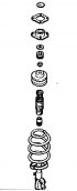
Front suspension strut — removal and repair
1. The upper parts of the front suspension strut have been modified in two places to eliminate detonation noise. Changes were made to virtually all of the upper...
1. The upper parts of the front suspension strut have been modified in two places to eliminate detonation noise. Changes were made to virtually all of the upper...
Plastic body parts — repair
1. With the increase in the number of plastic body parts used by car manufacturers (such as bumpers, spoilers and, in some cases, main body panels), the question of...
1. With the increase in the number of plastic body parts used by car manufacturers (such as bumpers, spoilers and, in some cases, main body panels), the question of...

Door Trim Panel (Late Models) — removal and installation
1. On later models, the power window switch is mounted in the inside door handle cover. The door pocket is also enlarged and includes a spring-loaded cover that hides...
1. On later models, the power window switch is mounted in the inside door handle cover. The door pocket is also enlarged and includes a spring-loaded cover that hides...

Instrument/Front Panel (Late Models) — removal and installation
1. The procedure is similar to that described in Section 11 Chapter 21 , but with some comments. The figure lists the parts in their removal order. Instrument/dashboard...
1. The procedure is similar to that described in Section 11 Chapter 21 , but with some comments. The figure lists the parts in their removal order. Instrument/dashboard...

Hatch (late models) — general information
1. The sunroof parts installed on later models are shown in the figure (photo). For more information about the sunroof, please contact Section 11, Chapter 34 . A...
1. The sunroof parts installed on later models are shown in the figure (photo). For more information about the sunroof, please contact Section 11, Chapter 34 . A...

Fuse Box (Late Models) — general information
Disassembled view of the main fuse box 1. In addition to the fuse box located below the instrument panel on the driver's side, the main fuse box is located on the left...
Disassembled view of the main fuse box 1. In addition to the fuse box located below the instrument panel on the driver's side, the main fuse box is located on the left...

Headlight (late models) — removal and installation
1. On later models, the headlights on each side of the grille are combined into one unit. 2. The removal and installation procedure is basically as described in Section...
1. On later models, the headlights on each side of the grille are combined into one unit. 2. The removal and installation procedure is basically as described in Section...

Headlight (late models) — adjustment
1. Contact Section 12, Chapter 9 ; the location of the adjustment screws is shown in the figure. Location of the adjustment screw on a later model headlight
1. Contact Section 12, Chapter 9 ; the location of the adjustment screws is shown in the figure. Location of the adjustment screw on a later model headlight

Light Bulbs (Late Models) — replacement
1. There are two sizes of warning lights on the rear of the instrument panel on later models, the replacement procedure remains the same as described in Section 12,...
1. There are two sizes of warning lights on the rear of the instrument panel on later models, the replacement procedure remains the same as described in Section 12,...

Radio (late models) — removal and installation
1. To remove, you need to release the side clips of two special plates to remove the radio from the panel, these can be found at your Mazda dealer or auto radio...
1. To remove, you need to release the side clips of two special plates to remove the radio from the panel, these can be found at your Mazda dealer or auto radio...

Instrument cluster (late models) — removal and installation
Exploded view of the analog instrument panel of later models 1. Printed circuit board panel; 2. Backlight plate; 3. Front cover; 4. Speedometer; 5. Tachometer; 6. Fuel...
Exploded view of the analog instrument panel of later models 1. Printed circuit board panel; 2. Backlight plate; 3. Front cover; 4. Speedometer; 5. Tachometer; 6. Fuel...

Instrument Cluster (Late Models) — removal and repair
Exploded view of the analog instrument panel of later models 1. Printed circuit board panel; 2. Backlight plate; 3. Front cover; 4. Speedometer; 5. Tachometer; 6. Fuel...
Exploded view of the analog instrument panel of later models 1. Printed circuit board panel; 2. Backlight plate; 3. Front cover; 4. Speedometer; 5. Tachometer; 6. Fuel...

Instrument cluster switch (late models) — removal and installation
1. Disconnect the negative cable from the battery. 2. Lower the tilt steering wheel (if any). Otherwise, remove the steering wheel completely. 3. Remove the screws from...
1. Disconnect the negative cable from the battery. 2. Lower the tilt steering wheel (if any). Otherwise, remove the steering wheel completely. 3. Remove the screws from...

Upper side light indicator — removal and installation
1. Disconnect the negative battery cable. 2. Remove the covers from the surroundings. 3. At the same time, move the rearview mirror all the way back and down, and pull...
1. Disconnect the negative battery cable. 2. Remove the covers from the surroundings. 3. At the same time, move the rearview mirror all the way back and down, and pull...

Instrument cluster backlight rheostat — removal and installation
1. Remove the rheostat from the instrument panel and disconnect the wiring (photo). Removing the rheostat backlight bulb 2. Assembly is carried out in reverse order.
1. Remove the rheostat from the instrument panel and disconnect the wiring (photo). Removing the rheostat backlight bulb 2. Assembly is carried out in reverse order.

Lower Instrument Panel Switch Panel — removal and installation
1. Carefully remove the panel from the dashboard and disconnect the electrical wiring (photo). Removing the lower instrument panel switch panel 2. Assembly is carried...
1. Carefully remove the panel from the dashboard and disconnect the electrical wiring (photo). Removing the lower instrument panel switch panel 2. Assembly is carried...

Digital Watch — removal and installation
1. Remove the surround from the instrument panel. 2. Remove the screws, remove the clock and disconnect the wiring (photo). Remove the screws... ...and remove the...
1. Remove the surround from the instrument panel. 2. Remove the screws, remove the clock and disconnect the wiring (photo). Remove the screws... ...and remove the...

Relays (EGI models) — location
Relay locations on EGI models 1. The location of the relays installed on the EGI model is shown in the figure (photo). Refer also to Section 12, Chapter 27 . Location of...
Relay locations on EGI models 1. The location of the relays installed on the EGI model is shown in the figure (photo). Refer also to Section 12, Chapter 27 . Location of...
This section is available on: russian, bulgarian, belarusian, ukrainian, serbian, croatian, romanian, polish, slovak, hungarian
Link in different formats to this section
TEXTHTMLBB Code
- General information
- Introduction to guide
- User manual
- Troubleshooting
- Maintenance
- Power unit
- 4-cylinder engines
- 6-cylinder engines
- Engine overhaul
- Cooling and ventilation
- Power and exhaust systems
- Engine electrics
- Control system
- Transmission
- Mechanical gearbox
- Automatic gearbox
- Clutch and drive shafts
- Chassis
- Brake system
- Car suspension
- Steering
- Body
- Exterior (external elements)
- Interior (internal elements)
- Doors, windows and locks
- Electrical equipment
- Equipment and devices
- Electrical circuits
- General information
- User manual
- Maintenance
- Helpful hints
- Power unit
- Petrol engines 1.6 and 1.8
- Petrol engines 2.0
- 2.5 petrol engines
- Overhaul engines 1.6 and 1.8
- Overhaul engines 2.0 and 2.5
- Diesel engine 2.0
- Engine electrics
- Cooling system
- Air conditioner
- Carburetor Nikki 30/34
- Power system (1.6 and 1.8)
- Power system (2.0 and 2.5)
- Control system
- Transmission
- Mechanical gearbox
- Automatic gearbox
- Clutch and axles
- Chassis
- Brake system
- Suspension and wheels
- Steering
- Body
- Exterior (external elements)
- Interior (internal elements)
- Doors and windows
- Electrical equipment
- Equipment and devices
- Electrical circuits
- General information
- Introduction to manual
- Vehicle specifications
- Power unit
- Engine repair
- Lubrication system
- Cooling system
- Fuel system (carburetor)
- Fuel injection (FE)
- Fuel injection (DOHC)
- Fuel system (diesel)
- Ignition system
- Transmission
- Clutch
- Gearbox
- Drive shafts
- Chassis
- Front suspension
- Rear suspension
- Steering system
- Brake system
- Electrical equipment
- Equipment and devices
- Electrical circuits
- General information
- User manual
- Maintenance
- Power unit
- Gasoline engine
- Engine overhaul (gasoline)
- Diesel engine
- Cooling and heating
- Supply system
- Ignition system
- Emission reduction
- Transmission
- Clutch
- Mechanical gearbox
- Automatic gearbox
- Drive shafts
- Chassis
- Brake system
- Suspension and wheels
- Steering
- Body
- Exterior (external elements)
- Interior (internal elements)
- Electrical equipment
- Equipment and devices
- Power devices
- Electrical circuits
- General information
- User manual
- Maintenance
- Troubleshooting
- Late models
- Power unit
- Engine in car
- Engine overhaul
- Cooling and heating system
- Fuel and exhaust system
- Engine electrical system
- Emission control system
- Transmission
- Mechanical gearbox
- Automatic gearbox
- Clutch and drive shafts
- Chassis
- Brake system
- Suspension and wheels
- Steering
- Body
- Exterior (external elements)
- Interior (internal elements)
- Electrical equipment
- Equipment and devices
- Lighting and lamps
- Electrical circuits