
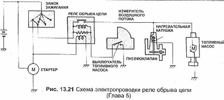
Open Circuit Relay Wiring Diagram
1. Open circuit relay (on the right side of the barrier) supplies current to the fuel pump and air valve only when the engine is running or starting. When the engine is stopped, the circuit is opened by the fuel pump switch located on the air flow meter.
2. With the ignition on, use a voltmeter with probes to check the clamps on the relay wiring and check for 12 volts at the Fr and B clamps. With the airflow meter plate manually open, check for 12 volts at the Fr and B clamps.
3. Disconnect and ground the ignition coil high voltage wire, then have a second person turn the ignition key to the start position and check for 12 volts at the Fr, B, and STA terminals.
4. Remove the connector from the relay and, using an ohmmeter, check that the resistance between terminals STA and E1 is 15-30 ohms, between terminals B and Fc is 80-150 ohms, and between terminals B and Fr is infinity.
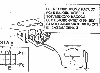
EGI Open Circuit Relay Connector Clip
5. Replace the relay if it is defective.