
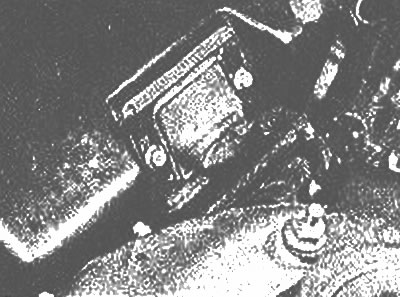
Clamping plate for airflow meter wire connector
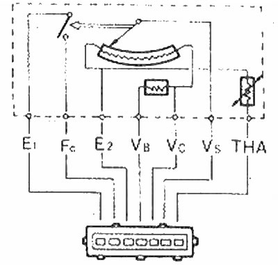
2. Turn on the ignition, then using a voltmeter with directional probes, check the voltage between each connector terminal and ground. The battery voltage should be at the terminals marked FC and VB, between 6 and 10 Volts at the VC terminal and between 0.7 and 2.7 Volts at the VS terminal.
3. If voltages are not correct, check wiring and main fuse.
4. Remove fastening and disconnect a socket of electroconducting from a measuring instrument of an air flow.
5. Using an ohmmeter, at terminals E2 and VS of the connector, check that the resistance is greater than 20 ohms. At terminals E2 and VC, the resistance must be between 100 and 300 ohms. on terminals E2 and VB from 200 to 400 ohms and on terminals E1 and FC - infinity.
6. The resistance at terminals E2 and THA depends on the air temperature within the air filter. Remove the air filter cover (photo), and using a thermometer, heat the source (e.g. a hot air gun) to check the resistance as given in the Specifications.
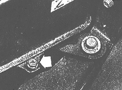
Bolt of fastening of a cover of the air filter (marked with an arrow)
7. Manually open the inner plate of the airflow meter and check. that the resistance at terminals E2 and VS is less than 400 ohms. There should be zero resistance across terminals E1 and FC.
EGI Airflow Meter Connector Clamp | 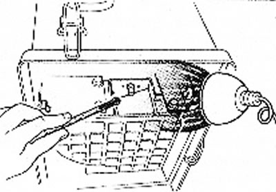
Air filter heating |
8. Check that the inner plate moves freely and, if necessary, use compressed air to clear any obstructions and deposits.
9. Install the air filter cover and wiring connector.