


Equipment and devices Mazda 626 (3rd and 4th gen)

Electrical system specifications
Incandescent lamp, Power Front: Headlights - 65/60 Dimensions - 5 Front turn - 21 Front side marker lights - 5 Salon: Lighting fixture - 10 Individual lighting - 6...
Incandescent lamp, Power Front: Headlights - 65/60 Dimensions - 5 Front turn - 21 Front side marker lights - 5 Salon: Lighting fixture - 10 Individual lighting - 6...
General description of the electrical system
The electrical system is 12 volts, ground negative. The on-board network is powered by a lead-acid battery, which is recharged by a generator. This Section covers the...
The electrical system is 12 volts, ground negative. The on-board network is powered by a lead-acid battery, which is recharged by a generator. This Section covers the...
Electrical System Troubleshooting — general description
A typical electrical circuit consists of any switches, relays, motors, etc., connected by wiring and connectors to the battery and chassis. Electrical connection...
A typical electrical circuit consists of any switches, relays, motors, etc., connected by wiring and connectors to the battery and chassis. Electrical connection...

Fuses — general description
The vehicle's electrical circuits are protected by a combination of fuses, reverse current relays and fusible links. The fuse box combines the fuse box, harnesses and...
The vehicle's electrical circuits are protected by a combination of fuses, reverse current relays and fusible links. The fuse box combines the fuse box, harnesses and...

General description of fuse links
In addition to fuses, the wiring is protected by fusible links. These connections are used in circuits that are not normally connected, such as the ignition circuit. The...
In addition to fuses, the wiring is protected by fusible links. These connections are used in circuits that are not normally connected, such as the ignition circuit. The...

Adjustable shock absorber actuator with three-pin connector — checking
1. Remove the shock absorber actuator, open and disconnect the connector ( Section 10 ). 2. Use an ohmmeter to measure the resistance across the Sport (L to B) and...
1. Remove the shock absorber actuator, open and disconnect the connector ( Section 10 ). 2. Use an ohmmeter to measure the resistance across the Sport (L to B) and...

Combination switch — removal and installation
1. Disconnect the negative battery cable. 2. Remove the steering wheel ( Section 10 ). 3. Remove the screws and separate the steering column trim halves (photo)....
1. Disconnect the negative battery cable. 2. Remove the steering wheel ( Section 10 ). 3. Remove the screws and separate the steering column trim halves (photo)....

Ignition Switch/Steering Wheel Lock — removal and installation
1. Remove the steering wheel ( Section 10 ) and combination switch ( Chapter 6 ) to provide access to the ignition switch. 2. Drill out the ignition switch mounting...
1. Remove the steering wheel ( Section 10 ) and combination switch ( Chapter 6 ) to provide access to the ignition switch. 2. Drill out the ignition switch mounting...

Radio and speakers removal and installation
Location of radio parts and speakers Radio 1. Disconnect the negative cable from the battery. 2. Remove the side panels of the center console. 3. Remove the radio...
Location of radio parts and speakers Radio 1. Disconnect the negative cable from the battery. 2. Remove the side panels of the center console. 3. Remove the radio...

Instrument cluster board — removal and installation
The arrangement of the instrument panel components 1. Upper instrument panel cover; 2. Cover of measuring instruments; 3. Switch panel; 4. Switch panel screws; 5. Left...
The arrangement of the instrument panel components 1. Upper instrument panel cover; 2. Cover of measuring instruments; 3. Switch panel; 4. Switch panel screws; 5. Left...

Front panel instruments — removal and installation
Location of instrument panel meters on the board (analog) 1. Glass screw; 2. Front dashboard glass; 3. PCB screw; 4. Printed circuit board; 5. Panel; 6. Protective...
Location of instrument panel meters on the board (analog) 1. Glass screw; 2. Front dashboard glass; 3. PCB screw; 4. Printed circuit board; 5. Panel; 6. Protective...

Dashboard Switches — removal and installation
Location of the switch panel on the left 1. Suspension screws; 2. Cover screw; 3. Suspension; 4. Screws and cover; 5. Cover screws; 6. Lid; 7. Switch cover; 7. Screw; 9....
Location of the switch panel on the left 1. Suspension screws; 2. Cover screw; 3. Suspension; 4. Screws and cover; 5. Cover screws; 6. Lid; 7. Switch cover; 7. Screw; 9....

Heater control — removal, installation and adjustment
1. Disconnect the negative battery cable. 2. Remove the air conditioner switch assembly, ventilation grille and disconnect them to access the control mounting screws...
1. Disconnect the negative battery cable. 2. Remove the air conditioner switch assembly, ventilation grille and disconnect them to access the control mounting screws...

Windshield wiper motor and linkage assembly — removal and installation
Location of windshield wiper assemblies in the assembly 1. Windshield wiper blade; 2. Wiper nut and arm; 3. Hood; 4. Service cover; 5. Bolts and washers of the traction...
Location of windshield wiper assemblies in the assembly 1. Windshield wiper blade; 2. Wiper nut and arm; 3. Hood; 4. Service cover; 5. Bolts and washers of the traction...

Rear Window Wiper Assembly — removal and installation
Rear wiper assembly components location 1. Windshield wiper blade; 2. Windshield wiper arm; 3. Rubber seal; 4. Suspension; 5. Windshield wiper motor 1. Disconnect the...
Rear wiper assembly components location 1. Windshield wiper blade; 2. Windshield wiper arm; 3. Rubber seal; 4. Suspension; 5. Windshield wiper motor 1. Disconnect the...

Electric Radio Antenna — removal and installation
Installation details for a radio antenna with an electric drive 1. Remove the under-dash cover, glove box, heater duct and fan assembly. 2. Remove the side trim and...
Installation details for a radio antenna with an electric drive 1. Remove the under-dash cover, glove box, heater duct and fan assembly. 2. Remove the side trim and...
Rear Window Defogger (Electric) — inspection and repair
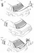
Rear window defroster assembly locations 1. Switch; 2. Anti-noise filter 1. It consists of a rear window with multiple horizontal elements that are sealed into the glass...
Rear window defroster assembly locations 1. Switch; 2. Anti-noise filter 1. It consists of a rear window with multiple horizontal elements that are sealed into the glass...
Sound warning system — general description
1. On models equipped with such devices, an audible warning alerts the driver to various faults and errors using four different signals. 2. The system and functions...
1. On models equipped with such devices, an audible warning alerts the driver to various faults and errors using four different signals. 2. The system and functions...

Speed control system — general description
Speed control system parts 1. Main switch; 2. Control switch; 3. Control unit; 4. Clutch feed switch; 5. Brake pedal switch; 6. Throttle actuator; 7. Switch, inhibitor...
Speed control system parts 1. Main switch; 2. Control switch; 3. Control unit; 4. Clutch feed switch; 5. Brake pedal switch; 6. Throttle actuator; 7. Switch, inhibitor...

Fuel and temperature gauges — checking
1. If the fuel level or temperature gauges are not giving accurate readings, the problem may be in the gauge or sensor. Using simple equipment (multimeter and a set of...
1. If the fuel level or temperature gauges are not giving accurate readings, the problem may be in the gauge or sensor. Using simple equipment (multimeter and a set of...

Relay — identification and replacement
1. The number and function of the installed relays varies according to the model and equipment. Typical ones are shown in the figure. Location and functions of the relay...
1. The number and function of the installed relays varies according to the model and equipment. Typical ones are shown in the figure. Location and functions of the relay...
Speedometer Drive Cable — removal and installation
1. Remove the clamp bolt and remove the speedometer drive cable with the mechanism from the transmission. Cm. Section 1, Chapter 4 . 2. Partially remove the instrument...
1. Remove the clamp bolt and remove the speedometer drive cable with the mechanism from the transmission. Cm. Section 1, Chapter 4 . 2. Partially remove the instrument...

Washer pumps — removal and installation
Headlight washer parts 1. Reservoir; 2. Pump; 3. Hoses; 4. Check valve; 5. Jets; 6. Control switch 1. All models have a windshield washer pump. Depending on the...
Headlight washer parts 1. Reservoir; 2. Pump; 3. Hoses; 4. Check valve; 5. Jets; 6. Control switch 1. All models have a windshield washer pump. Depending on the...
This section is available on: russian, bulgarian, belarusian, ukrainian, serbian, croatian, romanian, polish, slovak, hungarian
More sections on repairs of other Mazda models
• Electrical equipment: Equipment and devices Mazda Familia 6 (1989-1994)
• Electrical equipment: Equipment and devices Mazda3 BK (2003-2009)
• Electrical equipment: Equipment and devices Mazda6 GG (2002-2008)
• Electrical equipment: Equipment and devices Mazda CX-5KE (2012-2017)
• Electrical equipment: Equipment and devices Mazda 121 (3) (1996-2003)
• Electrical equipment: Equipment and devices Mazda Familia 6 (1989-1994)
• Electrical equipment: Equipment and devices Mazda3 BK (2003-2009)
• Electrical equipment: Equipment and devices Mazda6 GG (2002-2008)
• Electrical equipment: Equipment and devices Mazda CX-5KE (2012-2017)
• Electrical equipment: Equipment and devices Mazda 121 (3) (1996-2003)
Link in different formats to this section
TEXTHTMLBB Code
- General information
- Introduction to guide
- User manual
- Troubleshooting
- Maintenance
- Power unit
- 4-cylinder engines
- 6-cylinder engines
- Engine overhaul
- Cooling and ventilation
- Power and exhaust systems
- Engine electrics
- Control system
- Transmission
- Mechanical gearbox
- Automatic gearbox
- Clutch and drive shafts
- Chassis
- Brake system
- Car suspension
- Steering
- Body
- Exterior (external elements)
- Interior (internal elements)
- Doors, windows and locks
- Electrical equipment
- Equipment and devices
- Electrical circuits
- General information
- User manual
- Maintenance
- Helpful hints
- Power unit
- Petrol engines 1.6 and 1.8
- Petrol engines 2.0
- 2.5 petrol engines
- Overhaul engines 1.6 and 1.8
- Overhaul engines 2.0 and 2.5
- Diesel engine 2.0
- Engine electrics
- Cooling system
- Air conditioner
- Carburetor Nikki 30/34
- Power system (1.6 and 1.8)
- Power system (2.0 and 2.5)
- Control system
- Transmission
- Mechanical gearbox
- Automatic gearbox
- Clutch and axles
- Chassis
- Brake system
- Suspension and wheels
- Steering
- Body
- Exterior (external elements)
- Interior (internal elements)
- Doors and windows
- Electrical equipment
- Equipment and devices
- Electrical circuits
- General information
- Introduction to manual
- Vehicle specifications
- Power unit
- Engine repair
- Lubrication system
- Cooling system
- Fuel system (carburetor)
- Fuel injection (FE)
- Fuel injection (DOHC)
- Fuel system (diesel)
- Ignition system
- Transmission
- Clutch
- Gearbox
- Drive shafts
- Chassis
- Front suspension
- Rear suspension
- Steering system
- Brake system
- Electrical equipment
- Equipment and devices
- Electrical circuits
- General information
- User manual
- Maintenance
- Power unit
- Gasoline engine
- Engine overhaul (gasoline)
- Diesel engine
- Cooling and heating
- Supply system
- Ignition system
- Emission reduction
- Transmission
- Clutch
- Mechanical gearbox
- Automatic gearbox
- Drive shafts
- Chassis
- Brake system
- Suspension and wheels
- Steering
- Body
- Exterior (external elements)
- Interior (internal elements)
- Electrical equipment
- Equipment and devices
- Power devices
- Electrical circuits
- General information
- User manual
- Maintenance
- Troubleshooting
- Late models
- Power unit
- Engine in car
- Engine overhaul
- Cooling and heating system
- Fuel and exhaust system
- Engine electrical system
- Emission control system
- Transmission
- Mechanical gearbox
- Automatic gearbox
- Clutch and drive shafts
- Chassis
- Brake system
- Suspension and wheels
- Steering
- Body
- Exterior (external elements)
- Interior (internal elements)
- Electrical equipment
- Equipment and devices
- Lighting and lamps
- Electrical circuits