


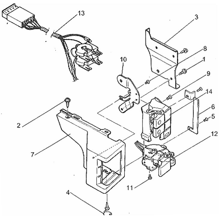
Location of the switch panel on the left
1. Suspension screws; 2. Cover screw; 3. Suspension; 4. Screws and cover; 5. Cover screws; 6. Lid; 7. Switch cover; 7. Screw; 9. Switch screw; 10. Suspension; 11. Light switch screws; 12. Light switch; 13. Wiring harness; 14. Hazard warning light switch and rear window defroster switch
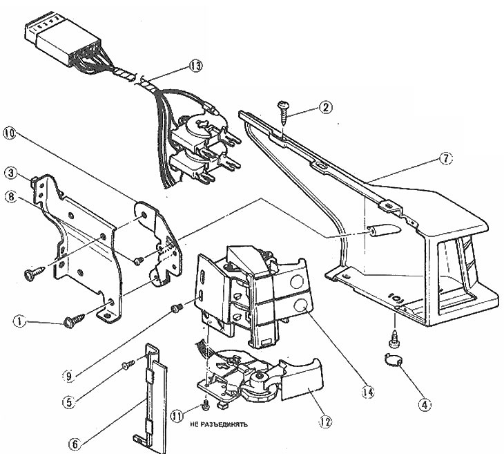
Location of the switch panel components on the right
1. Suspension screws; 2. Casing screws; 3. Suspension; 4. Screws and caps; 5. Cover screws; 6. Lid; 7. Switch cover; 8. Suspension screw; 9. Casing screws; 10. Suspension; 11. Windscreen wiper switch screws; 12. Windshield wiper switch; 13. Wiring harness; 14. Windshield washer switch and single stroke wiper switch
1. Disconnect the negative cable from the battery.
Switch panels
2. Remove the instrument panel (Chapter 12).
3. Remove the mounting screws, disconnect the wiring connector and the corresponding switches as an assembly from the meter board.
4. Assembly is carried out in reverse order.
The switches are not on the panel
5. Carefully pull the switch out of the socket, disconnect the wiring harness and remove the switch.
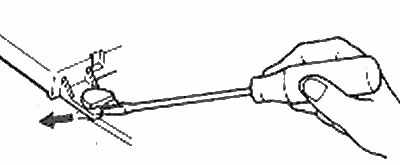
Disconnect the switch panel wiring harness by pressing in the direction shown with a straight-blade screwdriver
6. Assembly is carried out in reverse order.
(Based on website data www.MazBook.ru)