MazBook.ru
English Русский
Български
Беларускі
Український
Српски
Hrvatski
Română
Polski
Slovenský
Magyar
• Bookmark • Sitemap • Contacts •   
Cars Opel Cars Ford Cars Volkswagen Cars Audi Cars Kia Cars Renault Cars Peugeot


Familia Capella Mazda3 Mazda6 CX-? Others Articles
Capella 3 (1982-1992, petrol) Capella 3 and 4 (1982-1992) Capella 4 (1987-1992) Capella 5 (1991-1997) Capella 6 (1997-2005, petrol)

Fuel and temperature gauges — checking (Mazda Capella GC)

  • Home
  • Mazda Capella
  • Capella GC (1982-1992)
  • Electrical equipment
  • Equipment and devices
  • Fuel and temperature gauges — checking
0
Contents: Fuel level indicator ⇓ Fuel level indicator sensor ⇓ Temperature indicator ⇓ Temperature indicator sensor ⇓
1. If the fuel level or temperature gauges are not giving accurate readings, the problem may be in the gauge or sensor. Using simple equipment (multimeter and a set of resistors) you can check the meters and sensors.

Fuel level indicator


2. Access the fuel level sensor by removing the rear seat and inspection cover. Disconnect the electrical wiring connector.

3. Connect a resistor of known value from 8 to 96 ohms between the "Y" connector and ground (car metal). Make sure no other wires are shorted to ground, then turn the ignition on.

4. Allow the meter to stabilize for two minutes, then compare the expected measurement with the actual measurement.

5. Repeat the test, if possible, with other resistor values within the stated range. Before replacing resistors, turn off the ignition.

6. If the meter shows "full" or "empty" regardless of the resistor value, the wiring to the meter may be short-circuited or damaged, respectively. In other words, inaccurate data due to damage in the meter.

Checking the fuel gauge

Checking the fuel gauge
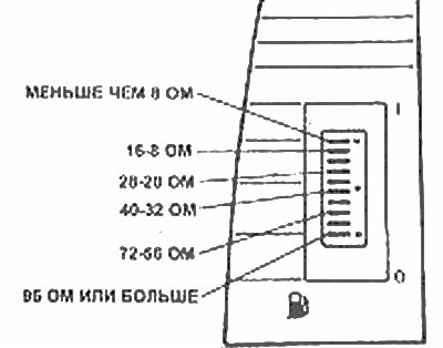
Fuel level indicator readings at different resistances

Fuel level indicator readings at different resistances


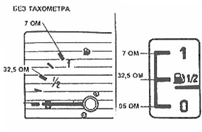
Analogue fuel gauge readings for different resistances

Analogue fuel gauge readings for different resistances


Fuel level indicator sensor


7. Remove the mounting screws and take out the sensor.

Warning: Take appropriate precautions against spontaneous combustion and vapor intoxication. Remove the sensor from the vehicle.
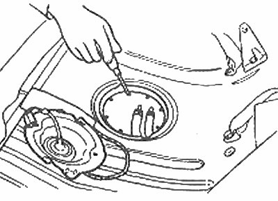

Removing the fuel level sensor

Removing the fuel level sensor


8. Connect the multimeter, set the resistance to be measured to the sensor terminals. Move the float up and down, compare the resistance in different positions with the values.
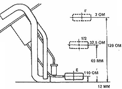
Fuel level indicator sensor resistance values

Fuel level indicator sensor resistance values


9. If the resistance does not change as defined, the sensor must be replaced. Finally, install the sensor.

Temperature indicator


10. Disconnect the electrical connector from the temperature gauge sensor (located behind the thermostat housing).

11. Connect a resistor of known value and within the range shown in the figure between the sensor connector and ground.

12. Make sure the wires are not shorted to ground, then turn on the ignition. Allow the meter to stabilize for two minutes, then compare the expected reading to the actual reading. Repeat with other resistors if possible.
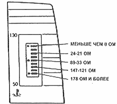
Electronic temperature indicator data for different resistances

Electronic temperature indicator data for different resistances


13. If the meter shows maximum or minimum, regardless of the resistor value, then the wiring is short-circuited or damaged.
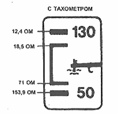
Analog temperature gauge data for different resistances - models with tachometer

Analog temperature gauge data for different resistances - models with tachometer
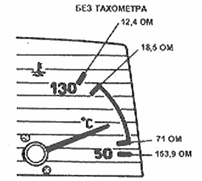
Analog temperature gauge data for various resistances - models without tachometer

Analog temperature gauge data for various resistances - models without tachometer


Temperature indicator sensor


14. Drain the fluid from the cooling system below the sensor level. Unscrew the sensor and remove it.

15. Hold the sensor on the water tray so that the light bulb is submerged. Connect the multimeter, set to resistance measurement, to the housing and clamp of the block. Heat the water to 80°C: the resistance at this temperature should be 53.5±4.2 Ohm.
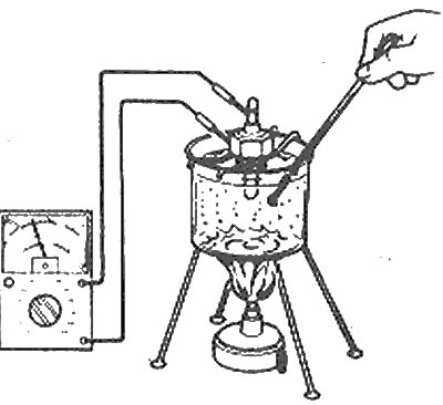
Testing the temperature gauge sensor

Testing the temperature gauge sensor


16. If the resistance is outside the limits, replace the sensor.

17. Install the sensor and fill the cooling system.
This article is available at: russian, bulgarian, belarusian, ukrainian, serbian, croatian, romanian, polish, slovak, hungarian
This text was checked by: Evdokia Filimonova
Share with friends on social networks:

Previous
Capella 3 » Equipment and devices
Next

Speed control system — general description
Sound warning system — general description
Rear Window Defogger (Electric) — inspection and repair
Electric Radio Antenna — removal and installation
Rear Window Wiper Assembly — removal and installation
Relay — identification and replacement
Speedometer Drive Cable — removal and installation
Washer pumps — removal and installation
More articles on repairing other Mazda models
Checking the fuel supply pressure Mazda Familia 5 (1985-1989)
Checking for fuel leaks after installing the pump unit (diesel) Mazda3 BK (2003-2009)
Checking for fuel leaks Mazda6 GG (2002-2008)
Checking fuel injectors of the high-pressure fuel pump Mazda CX-5KE (2012-2017)
Checking the fuel temperature sensor of the injection pump Mazda BT-50 (1) (2006-2011)
Link in different formats to this article
Comments and feedback from visitors
No comments yet


How much will 26 + 10 ?


Capella 6 (1997-2005, petrol) 
  • General information
  • Introduction to guide
  • User manual
  • Troubleshooting
  • Maintenance
  • Power unit
  • 4-cylinder engines
  • 6-cylinder engines
  • Engine overhaul
  • Cooling and ventilation
  • Power and exhaust systems
  • Engine electrics
  • Control system
  • Transmission
  • Mechanical gearbox
  • Automatic gearbox
  • Clutch and drive shafts
  • Chassis
  • Brake system
  • Car suspension
  • Steering
  • Body
  • Exterior (external elements)
  • Interior (internal elements)
  • Doors, windows and locks
  • Electrical equipment
  • Equipment and devices
  • Electrical circuits
Capella 5 (1991-1997) 
  • General information
  • User manual
  • Maintenance
  • Helpful hints
  • Power unit
  • Petrol engines 1.6 and 1.8
  • Petrol engines 2.0
  • 2.5 petrol engines
  • Overhaul engines 1.6 and 1.8
  • Overhaul engines 2.0 and 2.5
  • Diesel engine 2.0
  • Engine electrics
  • Cooling system
  • Air conditioner
  • Carburetor Nikki 30/34
  • Power system (1.6 and 1.8)
  • Power system (2.0 and 2.5)
  • Control system
  • Transmission
  • Mechanical gearbox
  • Automatic gearbox
  • Clutch and axles
  • Chassis
  • Brake system
  • Suspension and wheels
  • Steering
  • Body
  • Exterior (external elements)
  • Interior (internal elements)
  • Doors and windows
  • Electrical equipment
  • Equipment and devices
  • Electrical circuits
Capella 4 (1987-1992) 
  • General information
  • Introduction to manual
  • Vehicle specifications
  • Power unit
  • Engine repair
  • Lubrication system
  • Cooling system
  • Fuel system (carburetor)
  • Fuel injection (FE)
  • Fuel injection (DOHC)
  • Fuel system (diesel)
  • Ignition system
  • Transmission
  • Clutch
  • Gearbox
  • Drive shafts
  • Chassis
  • Front suspension
  • Rear suspension
  • Steering system
  • Brake system
  • Electrical equipment
  • Equipment and devices
  • Electrical circuits
Capella 3 and 4 (1982-1992) 
  • General information
  • User manual
  • Maintenance
  • Power unit
  • Gasoline engine
  • Engine overhaul (gasoline)
  • Diesel engine
  • Cooling and heating
  • Supply system
  • Ignition system
  • Emission reduction
  • Transmission
  • Clutch
  • Mechanical gearbox
  • Automatic gearbox
  • Drive shafts
  • Chassis
  • Brake system
  • Suspension and wheels
  • Steering
  • Body
  • Exterior (external elements)
  • Interior (internal elements)
  • Electrical equipment
  • Equipment and devices
  • Power devices
  • Electrical circuits
Capella 3 (1982-1992, petrol) 
  • General information
  • User manual
  • Maintenance
  • Troubleshooting
  • Late models
  • Power unit
  • Engine in car
  • Engine overhaul
  • Cooling and heating system
  • Fuel and exhaust system
  • Engine electrical system
  • Emission control system
  • Transmission
  • Mechanical gearbox
  • Automatic gearbox
  • Clutch and drive shafts
  • Chassis
  • Brake system
  • Suspension and wheels
  • Steering
  • Body
  • Exterior (external elements)
  • Interior (internal elements)
  • Electrical equipment
  • Equipment and devices
  • Lighting and lamps
  • Electrical circuits
MazBook.ru © 2018–2026 · Mobile version · Articles and news · Sitemap: EN BG BY UA RS HR RO PL SK HU · Feedback · Site search · Add to bookmarks Familia 5 (BF) · Familia 6 (BG) · Capella 3 (GC) · Capella 3 and 4 (GC) · Capella 4 (GD) · Capella 5 (GE) · Capella 6 (GF) · Mazda3 BK · Mazda6 GG · CX-5KE · Mazda 121 (3) · Mazda BT-50 (1) ·
By continuing to use the site, you agree to the use of cookies 🔐