


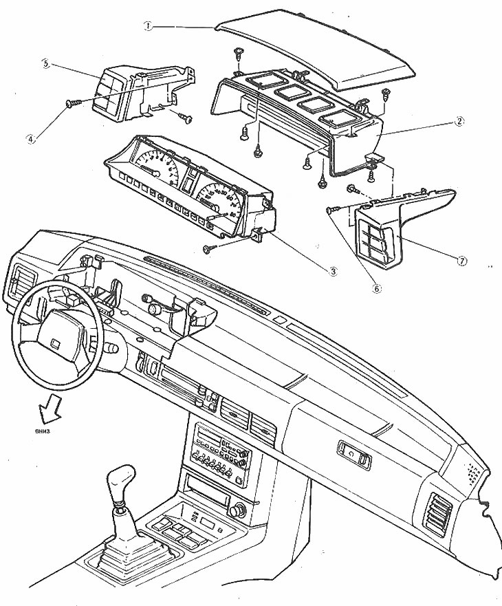
The arrangement of the instrument panel components
1. Upper instrument panel cover; 2. Cover of measuring instruments; 3. Switch panel; 4. Switch panel screws; 5. Left switch panel assembly; 6. Switch panel screws; 7. Right switch panel assembly
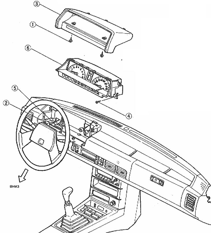
Layout of the instrument panel board components (models without switches on the panel)
1. Screws; 2. Lighting; 3. Panel cover; 4. Screws; 5. Electrical connectors; 6. Instrument cluster
1. Disconnect the negative battery cable and the lower regulator (if equipped) steering wheel.
2. Remove the top cover screws and remove the cover.
3. Remove the board mounting screws (photo).
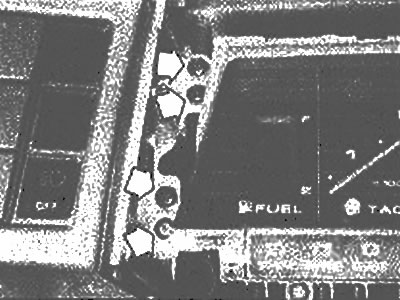
Left side instrument panel mounting screws (arrows)
Original version of the article on the website MAZBOOK.RU
4. Disconnect the speedometer drive cable.
5. Pull out the board from the inside, disconnect the electrical wires and remove it, and (if equipped) switches assembled from the instrument panel.
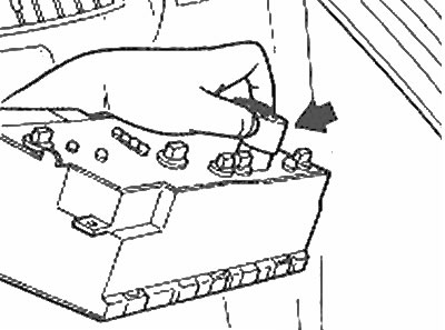
Disconnect the meter board connector (arrow) by squeezing the retaining clip
6. Assembly is carried out in reverse order.