


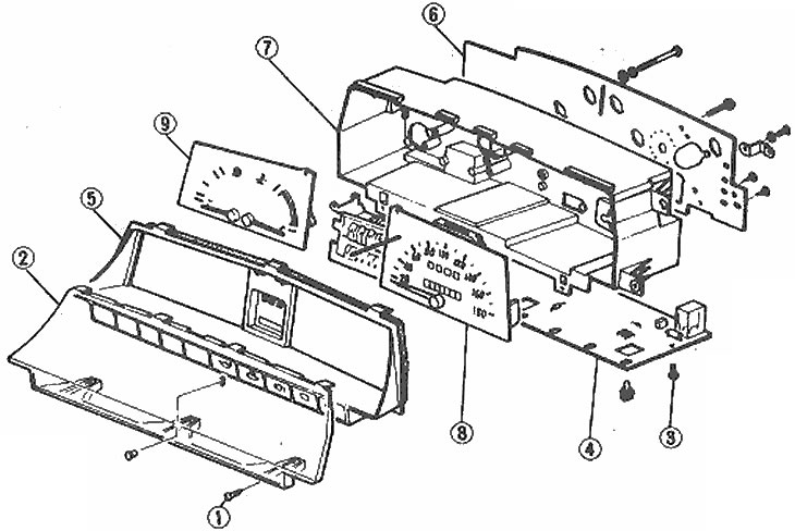
Location of instrument panel meters on the board (analog)
1. Glass screw; 2. Front dashboard glass; 3. PCB screw; 4. Printed circuit board; 5. Panel; 6. Protective panel; 7. Meter housing; 8. Speedometer; 9. Fuel level and water temperature indicators
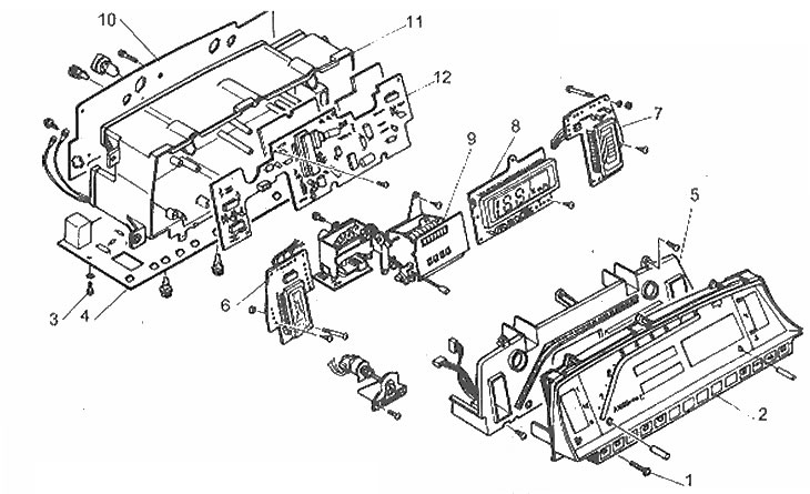
The arrangement of the electronic board components
1. Glass screw; 2. Front glass; 3. PCB base screw; 4. Printed circuit board base; 5. Tachometer and masking panel; 6. Fuel level indicator; 7. Water temperature indicator; 8. Speedometer; 9. Odometer; 10. Shield; 11. Meter housing; 12. Printed circuit board
1. Disconnect the negative battery cable.
2. Remove the instrument panel board (Chapter 12).
Analog instrument panel (pointer-type instruments)
3. Remove the front glass, circuit board and panel.
4. Remove the mounting bolt and remove the instruments from the panel.
5. Assembly is carried out in reverse order.
Electronic instrument panel
6. Remove the bulbs, sockets and mounting screws to remove the circuit board panel from the meter housing.
7. Remove the mounting screws and the front glass.
8. Remove the printed circuit board assembly and tachometer.
9. Remove the display switches assembly.
10. Remove the instrument panel backlight adjustment button assembly.
11. Remove the mounting screws and disconnect the speedometer, fuel and temperature gauges from the housing.
12. Assembly is carried out in reverse order.