


Electrical Equipment and Appliances Mazda 6 (GG)

General information about electrical equipment
Fig. 7.1. Electrical supply system of the Mazda 6: 1 – battery; 2 – alternating current generator; 3 – starter; 4 – ignition coil; 5 – spark plug; 6 – high voltage wires...
Fig. 7.1. Electrical supply system of the Mazda 6: 1 – battery; 2 – alternating current generator; 3 – starter; 4 – ignition coil; 5 – spark plug; 6 – high voltage wires...

Determining the source of the fault
An electrical circuit consists of an electrical element, switches, relays, electric motors, fuses, circuit breakers, wires and connectors that connect the current...
An electrical circuit consists of an electrical element, switches, relays, electric motors, fuses, circuit breakers, wires and connectors that connect the current...

Fuses — Description and Replacement
Fuses are used to interrupt a circuit when the current exceeds a certain value and to protect components and wires that could be damaged by too much current. A sudden...
Fuses are used to interrupt a circuit when the current exceeds a certain value and to protect components and wires that could be damaged by too much current. A sudden...
Relay — purpose and location
A relay is an electronically controlled switch that is typically used as follows: switches large currents remotely from the circuit in which the current flows, allowing...
A relay is an electronically controlled switch that is typically used as follows: switches large currents remotely from the circuit in which the current flows, allowing...

Removal and installation the alarm sensor
Disconnect the negative cable from the battery. Remove the upholstery. Disconnect the sensor connector. Fig. 7.75. Removing the security alarm sensor: 1 – connector; 2 –...
Disconnect the negative cable from the battery. Remove the upholstery. Disconnect the sensor connector. Fig. 7.75. Removing the security alarm sensor: 1 – connector; 2 –...

Removal and installation a security alarm siren
Disconnect the negative cable from the battery. Remove the trunk side trim on the left side. Fig. 7.76. Removing the security alarm siren: 1 – nut; 2 – connector; 3 –...
Disconnect the negative cable from the battery. Remove the trunk side trim on the left side. Fig. 7.76. Removing the security alarm siren: 1 – nut; 2 – connector; 3 –...
Immobilizer — enabling/blocking the key reprogramming function without using WDS or an analogue
Note: Enabling this feature allows you to register a key without a special device (WDS or similar). Disabling this feature prevents drivers from being able to reprogram...
Note: Enabling this feature allows you to register a key without a special device (WDS or similar). Disabling this feature prevents drivers from being able to reprogram...

Removal and installation the ignition switch
Note: Remove the lock only for replacement. In this case, reprogramming the immobilizer is not required. Disconnect the negative cable from the battery. Remove the...
Note: Remove the lock only for replacement. In this case, reprogramming the immobilizer is not required. Disconnect the negative cable from the battery. Remove the...

Immobilizer reprogramming procedure
Fig. 7.78. When a client has two or more valid keys Note: If you still cannot reprogram the immobilizer, check the number of working keys. Replace the key or perform the...
Fig. 7.78. When a client has two or more valid keys Note: If you still cannot reprogram the immobilizer, check the number of working keys. Replace the key or perform the...

Replacing or registering an additional key
Note: Unless otherwise specified, perform each operation within 30 seconds of the previous one. Fig. 7.79. If the client has only one or no valid keys 1. Make a new...
Note: Unless otherwise specified, perform each operation within 30 seconds of the previous one. Fig. 7.79. If the client has only one or no valid keys 1. Make a new...

Removal and installation the center panel module
Disable the anti-theft system (cars with anti-theft system). Disconnect the negative cable from the battery. Remove the glove box. Remove the rear console. Fig. 7.80....
Disable the anti-theft system (cars with anti-theft system). Disconnect the negative cable from the battery. Remove the glove box. Remove the rear console. Fig. 7.80....

Disassembling and assembling the central panel module
Attention! When disassembling the central panel module, lay a piece of cloth on the floor and place the removed elements on it. Attention! This will protect the panel...
Attention! When disassembling the central panel module, lay a piece of cloth on the floor and place the removed elements on it. Attention! This will protect the panel...

Disassembling and assembling the audio unit
Remove the audio unit. Fig. 7.83. Audio block components: 1 – lid (without top module); 2 – screw; 3 – top module; 4 – screw; 5 – lower module; 6 – screw; 7 – wiring...
Remove the audio unit. Fig. 7.83. Audio block components: 1 – lid (without top module); 2 – screw; 3 – top module; 4 – screw; 5 – lower module; 6 – screw; 7 – wiring...
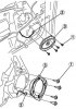
Removal and installation the front door speaker
Disconnect the negative cable from the battery. Remove the front door trim. Fig. 7.84. Removing the front door speaker: 1 – screw; 2 – connector; 3 – front door speaker...
Disconnect the negative cable from the battery. Remove the front door trim. Fig. 7.84. Removing the front door speaker: 1 – screw; 2 – connector; 3 – front door speaker...

Removal and installation the rear door speaker
Disconnect the negative cable from the battery. Remove the rear door trim. Fig. 7.86. Removing the front door speaker: 1 – screw; 2 – connector; 3 – front door speaker...
Disconnect the negative cable from the battery. Remove the rear door trim. Fig. 7.86. Removing the front door speaker: 1 – screw; 2 – connector; 3 – front door speaker...

Removal and installation a high frequency speaker
Disconnect the negative cable from the battery. Fig. 7.88. Audio block components: 1 – interior decoration; 2 – connector; 3 – screw; 4 – lid; 5 – speaker for...
Disconnect the negative cable from the battery. Fig. 7.88. Audio block components: 1 – interior decoration; 2 – connector; 3 – screw; 4 – lid; 5 – speaker for...

Removal and installation the interference suppression filter
Disconnect the negative cable from the battery. Fig. 7.90. Removing the interference suppression filter: 1 – nut; 2 – connector; 3 – noise suppression filter Remove in...
Disconnect the negative cable from the battery. Fig. 7.90. Removing the interference suppression filter: 1 – nut; 2 – connector; 3 – noise suppression filter Remove in...

Removal and installation the roof antenna
Disconnect the negative cable from the battery. Remove the upholstery. Fig. 7.91. Removing the roof antenna: 1 – antenna pin; 2 – antenna feeder; 3 – nut; 4 – antenna on...
Disconnect the negative cable from the battery. Remove the upholstery. Fig. 7.91. Removing the roof antenna: 1 – antenna pin; 2 – antenna feeder; 3 – nut; 4 – antenna on...

Car instrument cluster
Fig. 7.93. Instrument cluster of the Mazda 6: 1 – coolant temperature indicator; 2 – tachometer; 3 – speedometer; 4 – fuel level indicator; 5 – odometer and trip meter...
Fig. 7.93. Instrument cluster of the Mazda 6: 1 – coolant temperature indicator; 2 – tachometer; 3 – speedometer; 4 – fuel level indicator; 5 – odometer and trip meter...

Indication and alarm system
Main characteristics The CAN system is used to transmit control signals for the input/output of the communication circuit of the instrument cluster, sensors, warning...
Main characteristics The CAN system is used to transmit control signals for the input/output of the communication circuit of the instrument cluster, sensors, warning...

Installation diagram of the security system
Fig. 7.95. Installation diagram of the security system: 1 – security system control module; 2 – ignition key left in the lock reminder switch; 3 – direction indicator...
Fig. 7.95. Installation diagram of the security system: 1 – security system control module; 2 – ignition key left in the lock reminder switch; 3 – direction indicator...

Central Panel Module — Main Features
Fig. 7.96. Central panel module: 1 – central panel; 2 – audio block; 3 – main block; 4 – top module; 5 – lid (without top module); 6 – lower module; 7 – mounting board...
Fig. 7.96. Central panel module: 1 – central panel; 2 – audio block; 3 – main block; 4 – top module; 5 – lid (without top module); 6 – lower module; 7 – mounting board...

Remote control and remote control socket
Fig. 7.98. Remote control: 1 – remote control; 2 – nest; 3 – front view; 4 – top view; 5 – bottom view; 6 – infrared radio transmitter; 7 – infrared sensor; 8 – power...
Fig. 7.98. Remote control: 1 – remote control; 2 – nest; 3 – front view; 4 – top view; 5 – bottom view; 6 – infrared radio transmitter; 7 – infrared sensor; 8 – power...

Passive safety system — general information
The Supplemental Restraint System (SRS) includes two main subsystems: airbag system with gas generators; electrical system with impact sensors and fault diagnostic...
The Supplemental Restraint System (SRS) includes two main subsystems: airbag system with gas generators; electrical system with impact sensors and fault diagnostic...

Side airbag module
In the event of a side collision, the airbag is deployed (unfolds) after receiving a control signal from the SAS unit and distributes the impact to the chest area of the...
In the event of a side collision, the airbag is deployed (unfolds) after receiving a control signal from the SAS unit and distributes the impact to the chest area of the...

Seat belt components with pretensioner
Fig. 7.102. Components of a seat belt with pretensioner: 1 – spring block; 2 – guide plate; 3 – pretensioner cover; 4 – pipe; 5 – guide block; 6 – gas generator; 7 –...
Fig. 7.102. Components of a seat belt with pretensioner: 1 – spring block; 2 – guide plate; 3 – pretensioner cover; 4 – pipe; 5 – guide block; 6 – gas generator; 7 –...
Instructions for using seat belts
Seat belts should be placed on the parts of the body where strong bones are located. The belt should pass over the pelvic bone, chest and shoulder. Avoid placing the lap...
Seat belts should be placed on the parts of the body where strong bones are located. The belt should pass over the pelvic bone, chest and shoulder. Avoid placing the lap...
Automatic belt release lock mode
When installing and securing child restraints, it is necessary to switch the reel to the automatic locking mode. This will prevent the child restraint from moving...
When installing and securing child restraints, it is necessary to switch the reel to the automatic locking mode. This will prevent the child restraint from moving...
Seat belt with pretensioner
For more effective protection in the event of an accident, the seat belts installed on the driver and front passenger seats are equipped with pyrotechnic pretensioners...
For more effective protection in the event of an accident, the seat belts installed on the driver and front passenger seats are equipped with pyrotechnic pretensioners...
This section is available on: russian, bulgarian, belarusian, ukrainian, serbian, croatian, romanian, polish, slovak, hungarian
More sections on repairs of other Mazda models
• Electrical equipment: Equipment and devices Mazda Familia 5 (1985-1989)
• Electrical equipment: Equipment and devices Mazda Capella 5 (1991-1997)
• Electrical equipment: Equipment and devices Mazda3 BK (2003-2009)
• Electrical equipment: Equipment and devices Mazda CX-5KE (2012-2017)
• Electrical equipment: Equipment and devices Mazda 121 (3) (1996-2003)
• Electrical equipment: Equipment and devices Mazda Familia 5 (1985-1989)
• Electrical equipment: Equipment and devices Mazda Capella 5 (1991-1997)
• Electrical equipment: Equipment and devices Mazda3 BK (2003-2009)
• Electrical equipment: Equipment and devices Mazda CX-5KE (2012-2017)
• Electrical equipment: Equipment and devices Mazda 121 (3) (1996-2003)
Link in different formats to this section
TEXTHTMLBB Code
- User manual
- Vehicle description
- Keys, locks and alarms
- Controls and instruments
- Air conditioning and heater
- Seat adjustment
- Security systems
- Driving and operation
- Faults en route
- Maintenance
- Power unit
- Engine device
- Engine repair
- Lubrication system
- Cooling system
- Fuel system
- Exhaust system
- Electrical equipment of engines
- Control system
- Transmission
- Clutch
- Mechanical gearbox
- Automatic gearbox
- Drive shafts and hubs
- Chassis
- Suspension and wheels
- Steering
- Brake system
- Body
- Exterior (external elements)
- Interior (internal elements)
- Doors and windows
- Air conditioning and heater
- Electrical equipment
- Equipment and devices
- Power devices
- Lighting system
- Windshield wipers and washers