
MazBook.ru
English Русский
Български
Беларускі
Український
Српски
Hrvatski
Română
Polski
Slovenský
Magyar
• Bookmark • Sitemap • Contacts •   
Cars Opel Cars Ford Cars Volkswagen Cars Audi Cars Kia Cars Renault Cars Peugeot


Familia Capella Mazda3 Mazda6 CX-? Others Articles
Mazda6 GG (2002-2008)

Installation diagram of the security system (Mazda 6 GG)

  • Home
  • Mazda 6
  • Mazda6 GG (2002-2008)
  • Electrical equipment
  • Equipment and devices
  • Installation diagram of the security system
0
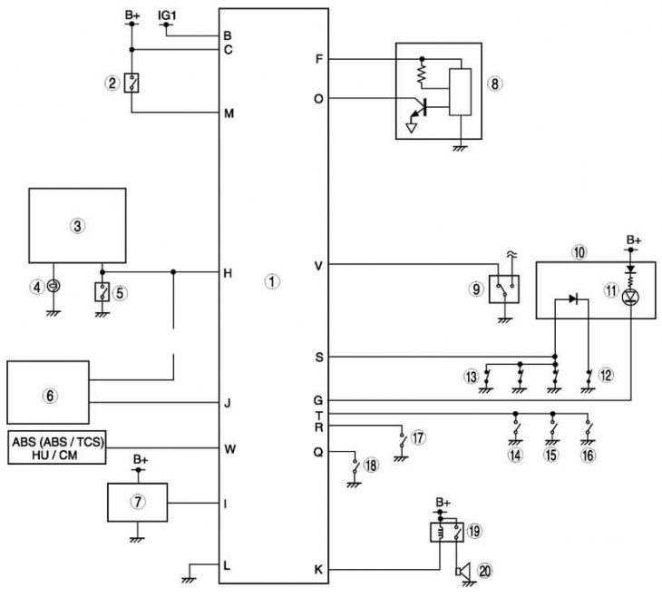
Fig. 7.95. Installation diagram of the security system: 1 – security system control module; 2 –…

Fig. 7.95. Installation diagram of the security system: 1 – security system control module; 2 – ignition key left in the lock reminder switch; 3 – direction indicator and hazard warning light switch; 4 – direction indicator; 5 – hazard warning switch; 6 – door lock timer unit; 7 – security alarm siren; 8 – security alarm sensor; 9 – Driver's door lock switch; 10 – instrument cluster; 11 – safety lamp; 12 – door limit switch (driver side); 13 – door limit switch (except driver's side); 14 – Passenger door lock switch; 15 – Rear door lock switch (right); 16 – Rear door lock switch (left); 17 – Engine compartment light switch (4SD), luggage compartment light switch (5HB); 18 – hood limit switch; 19 – horn relay; 20 – sound signal


The installation diagram of the security system is shown in Fig. 7.95.

[Based on website data: Mazbook.ru]
This article is available at: russian, bulgarian, belarusian, ukrainian, serbian, croatian, romanian, polish, slovak, hungarian
This text was checked by: Evdokia Filimonova
Share with friends on social networks:

Previous
Mazda6 GG » Equipment and devices
Next

Indication and alarm system
Car instrument cluster
Removal and installation the roof antenna
Removal and installation the interference suppression filter
Removal and installation a high frequency speaker
Central Panel Module — Main Features
Remote control and remote control socket
Passive safety system — general information
Side airbag module
Seat belt components with pretensioner
More articles on repairing other Mazda models
Structural diagram of the injection system Mazda Familia 5 (1985-1989)
Stereo system wiring diagram Mazda Capella 5 (1991-1997)
Electronic immobilizer (anti-theft system) Mazda3 BK (2003-2009)
Vacuum hose routing diagram for the intake system of a gasoline engine Mazda CX-5KE (2012-2017)
Diagram 2. Endura-E (I) Engine Management System Mazda 121 (3) (1996-2003)
Link in different formats to this article
Comments and feedback from visitors
No comments yet


How much will 16 + 22 ?


Mazda6 GG (2002-2008) 
  • User manual
  • Vehicle description
  • Keys, locks and alarms
  • Controls and instruments
  • Air conditioning and heater
  • Seat adjustment
  • Security systems
  • Driving and operation
  • Faults en route
  • Maintenance
  • Power unit
  • Engine device
  • Engine repair
  • Lubrication system
  • Cooling system
  • Fuel system
  • Exhaust system
  • Electrical equipment of engines
  • Control system
  • Transmission
  • Clutch
  • Mechanical gearbox
  • Automatic gearbox
  • Drive shafts and hubs
  • Chassis
  • Suspension and wheels
  • Steering
  • Brake system
  • Body
  • Exterior (external elements)
  • Interior (internal elements)
  • Doors and windows
  • Air conditioning and heater
  • Electrical equipment
  • Equipment and devices
  • Power devices
  • Lighting system
  • Windshield wipers and washers
MazBook.ru © 2018–2026 · Mobile version · Articles and news · Sitemap: EN BG BY UA RS HR RO PL SK HU · Feedback · Site search · Add to bookmarks Familia 5 (BF) · Familia 6 (BG) · Capella 3 (GC) · Capella 3 and 4 (GC) · Capella 4 (GD) · Capella 5 (GE) · Capella 6 (GF) · Mazda3 BK · Mazda6 GG · CX-5KE · Mazda 121 (3) · Mazda BT-50 (1) ·
By continuing to use the site, you agree to the use of cookies 🔐