


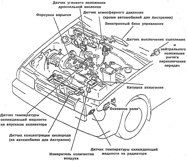
Installation locations of the main components of the fuel injection system of a non-turbocharged engine
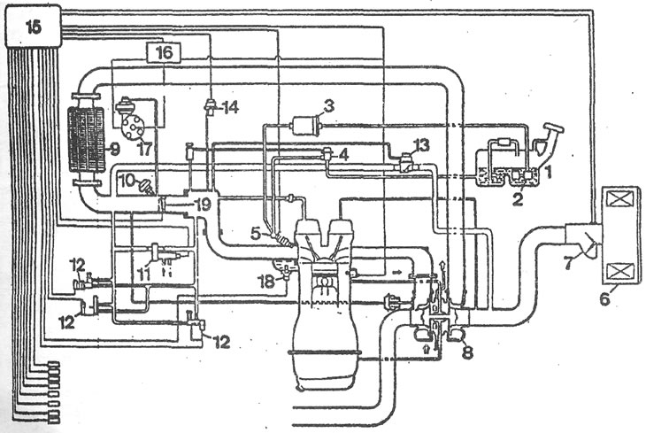
Structural diagram of the injection system: 1 - fuel tank; 2 - fuel pump; 3 - fuel filter; 4 - fuel pressure regulator; 5 - injection nozzle; 6 - air filter; 7 - air quantity meter; 8 - turbocharger*; 9 - heat exchanger*; 10 - forced idle pneumatic valve; 11 - additional air supply valve; 12 - electromagnetic valve for idle mixture compensation; 13 - Turbocharger restart valve*; 14 - Boost pressure sensor*; 15 - electronic control unit; 16 - Switch; 17 - ignition distributor sensor; 18 - coolant temperature sensor; 19 - throttle valve.
[For details, see the website: MAZBOOK.RU]