


Power supply and ignition of engines «E» Mazda 323 (BF)
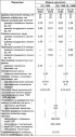
Technical characteristics of the power supply system
Fuel tank The fuel tank is stamped from sheet steel. It is installed in front of the rear axle under the floor of the car. Fuel tank capacity, l: 45. Fuel used: Super...
Fuel tank The fuel tank is stamped from sheet steel. It is installed in front of the rear axle under the floor of the car. Fuel tank capacity, l: 45. Fuel used: Super...

Technical characteristics of the ignition system
The engine ignition system is electronic, contactless. The ignition distributor sensor with vacuum and centrifugal ignition timing regulators has a contactless sensor...
The engine ignition system is electronic, contactless. The ignition distributor sensor with vacuum and centrifugal ignition timing regulators has a contactless sensor...

The structure and operating principle of the electronic contactless ignition system
Device The electronic contactless ignition system includes a sensor-distributor with a contactless sensor (pulse generator sensor) and high energy ignition coil. Like...
Device The electronic contactless ignition system includes a sensor-distributor with a contactless sensor (pulse generator sensor) and high energy ignition coil. Like...
Checking electrical characteristics
Checking voltage Using a voltmeter, measure the voltage in sequence at the following four points: when the ignition is on, the voltage "U" at the battery terminals must...
Checking voltage Using a voltmeter, measure the voltage in sequence at the following four points: when the ignition is on, the voltage "U" at the battery terminals must...

Removal and installation the ignition distributor sensor
Removal After unscrewing the fastening screws, remove the distributor sensor cover. Disconnect the vacuum hose from the distributor sensor. Disconnect the switch plug....
Removal After unscrewing the fastening screws, remove the distributor sensor cover. Disconnect the vacuum hose from the distributor sensor. Disconnect the switch plug....

Setting the ignition timing
Connect the stroboscope in accordance with the operating instructions, while connecting the stroboscope sensor clamp to the high-voltage wire of the ignition coil....
Connect the stroboscope in accordance with the operating instructions, while connecting the stroboscope sensor clamp to the high-voltage wire of the ignition coil....

Power supply system — device
Power supply system: 1 - air filter; 2 - air filter housing; 3 - lid; 4 - cold air supply hose; 5 - warm air supply hose; 6 - carburetor; 7 - fuel pump; 8 - fine fuel...
Power supply system: 1 - air filter; 2 - air filter housing; 3 - lid; 4 - cold air supply hose; 5 - warm air supply hose; 6 - carburetor; 7 - fuel pump; 8 - fine fuel...
Fuel pump — removal and installation
Removing and installing the fuel pump is not difficult. When installing the pump, pay attention to the correct connection of the fuel supply and delivery hoses to it.
Removing and installing the fuel pump is not difficult. When installing the pump, pay attention to the correct connection of the fuel supply and delivery hoses to it.
Checking the fuel supply pressure
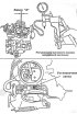
Disconnect the fuel supply hose to the carburetor from the pump. Attach a tee with a pressure gauge to the hose opening and to the pump branch pipe. Start the engine at...
Disconnect the fuel supply hose to the carburetor from the pump. Attach a tee with a pressure gauge to the hose opening and to the pump branch pipe. Start the engine at...

Aisan carburetor — device
Aisan emulsion type carburetor, two-chamber, with sequential opening of throttle valves, with automatic starting device. Aisan carburetor diagram: 1 - needle valve; 2 -...
Aisan emulsion type carburetor, two-chamber, with sequential opening of throttle valves, with automatic starting device. Aisan carburetor diagram: 1 - needle valve; 2 -...

Automatic carburetor starter
Automatic carburetor starter: 11 - air damper; 25 - bimetallic spring; 26 - pneumatic drive of the air damper; 27 - air damper opening thrust when engine speed...
Automatic carburetor starter: 11 - air damper; 25 - bimetallic spring; 26 - pneumatic drive of the air damper; 27 - air damper opening thrust when engine speed...
Idle and transition systems
When the engine is idling, the throttle valve of the 1st chamber 6 is closed. The idle system takes fuel from the emulsion well after the main fuel jet 3 and is fed to...
When the engine is idling, the throttle valve of the 1st chamber 6 is closed. The idle system takes fuel from the emulsion well after the main fuel jet 3 and is fed to...
Main dosing system
Fuel is supplied through needle valve 1 to the float chamber, in which float 2, mounted pivotally on an axis, maintains a constant fuel level in the chamber. From the...
Fuel is supplied through needle valve 1 to the float chamber, in which float 2, mounted pivotally on an axis, maintains a constant fuel level in the chamber. From the...
Accelerator pump
When the throttle valve of the 1st chamber is opened, cam 20, mounted on its axis, presses the lever and through the spring in the pusher acts on the diaphragm of the...
When the throttle valve of the 1st chamber is opened, cam 20, mounted on its axis, presses the lever and through the spring in the pusher acts on the diaphragm of the...

Setting the fuel level in the float chamber
Remove and turn over the carburetor cover. Measure the distance "X" between the plane of the cover joint and the lower point of the float (see fig.), which should be...
Remove and turn over the carburetor cover. Measure the distance "X" between the plane of the cover joint and the lower point of the float (see fig.), which should be...
Adjusting the starting clearance of the air damper
Warm up and stop the engine. Remove the air filter. Close the air damper completely, locking the throttle control sector. Disconnect the air hose from the air damper...
Warm up and stop the engine. Remove the air filter. Close the air damper completely, locking the throttle control sector. Disconnect the air hose from the air damper...
Adjusting the starting gap of the throttle valve of the 1st chamber
Remove the carburetor. Close the air damper completely, locking the throttle control sector on the fourth protrusion. Measure the gap between the throttle valve and the...
Remove the carburetor. Close the air damper completely, locking the throttle control sector on the fourth protrusion. Measure the gap between the throttle valve and the...
Adjusting the opening of the throttle valve of the 2nd chamber
Remove the carburetor. Turn the throttle valve of the 1st chamber until the throttle valve of the 2nd chamber begins to open. Without changing the position of the flaps,...
Remove the carburetor. Turn the throttle valve of the 1st chamber until the throttle valve of the 2nd chamber begins to open. Without changing the position of the flaps,...

Adjusting engine idle speed
Before adjusting the engine idle speed: disconnect the air hoses from the automatic starting device and unplug it; warm up the engine by running it at 2000 rpm until the...
Before adjusting the engine idle speed: disconnect the air hoses from the automatic starting device and unplug it; warm up the engine by running it at 2000 rpm until the...

Carburetor parts
Carburetor parts: 1 - lid; 2 - cover gasket; 3 - body; 4 - throttle body; 5 - spacer; 6 - viewing window of the float chamber with a fuel level indicator; 7 - float; 8 -...
Carburetor parts: 1 - lid; 2 - cover gasket; 3 - body; 4 - throttle body; 5 - spacer; 6 - viewing window of the float chamber with a fuel level indicator; 7 - float; 8 -...
Removal and installation the carburetor
Remove the air filter. Disconnect the hose from the carburetor fuel supply pipe. Disconnect the air hoses from the carburetor pneumatic drives. Disconnect the plug...
Remove the air filter. Disconnect the hose from the carburetor fuel supply pipe. Disconnect the air hoses from the carburetor pneumatic drives. Disconnect the plug...

Exhaust gas system
Exhaust system: 1 - exhaust manifold; 2 - heat shield; 3 - exhaust manifold flange gasket; 4 - exhaust manifold gasket; 5 - intake pipe; 6 - central pipe; 7 - main...
Exhaust system: 1 - exhaust manifold; 2 - heat shield; 3 - exhaust manifold flange gasket; 4 - exhaust manifold gasket; 5 - intake pipe; 6 - central pipe; 7 - main...
This section is available on: russian, bulgarian, belarusian, ukrainian, serbian, croatian, romanian, polish, slovak, hungarian
More sections on repairs of other Mazda models
• Power unit: Fuel and exhaust system Mazda Capella 3 (1982-1992, petrol)
• Power unit: Fuel system Mazda3 BK (2003-2009)
• Power unit: Fuel system Mazda6 GG (2002-2008)
• Power unit: Supply system Mazda CX-5KE (2012-2017)
• Power unit: Supply system Mazda 121 (3) (1996-2003)
• Power unit: Fuel and exhaust system Mazda Capella 3 (1982-1992, petrol)
• Power unit: Fuel system Mazda3 BK (2003-2009)
• Power unit: Fuel system Mazda6 GG (2002-2008)
• Power unit: Supply system Mazda CX-5KE (2012-2017)
• Power unit: Supply system Mazda 121 (3) (1996-2003)
Link in different formats to this section
TEXTHTMLBB Code
- General information
- Introduction to guide
- User manual
- Maintenance
- Power unit
- Petrol engines
- Diesel engines
- Lubrication system
- Cooling system
- Ignition system
- Supply system
- Carburetor
- Injection system
- Exhaust system
- Transmission
- Clutch
- Car gearbox
- Chassis
- Front suspension
- Rear suspension
- Steering
- Brake system
- Wheels and tires
- Body
- Body elements
- Doors and windows
- Body Care
- Electrical equipment
- Equipment and devices
- Power devices
- Heating system
- Lighting and headlights
- Windshield wipers and washers
- Wiring diagrams (since 1987)
- Wiring diagrams (since 1991)
- General information
- Vehicle data
- Model «E» engine
- Engine repair
- Cooling and lubrication system
- Power and ignition system
- Model «B» engine
- Engine repair
- Cooling and lubrication system
- Ignition system
- Power system (carburetor)
- Power system (injector)
- Transmission
- Clutch
- Mechanical gearbox
- Automatic gearbox
- Front wheel drive
- Chassis
- Steering
- Front suspension
- Rear suspension
- Brake system
- Electrical equipment
- Equipment and devices
- Electrical circuits
- Wiring diagrams (station wagon)