


Vehicle fuel system Mazda 3 (BK)

General information about the fuel system
Mazda 3 (GG) cars are equipped with new L-series engines. The features of the L-series engines are listed below: Fig. 2.53. Diagram of the fuel system control system of...
Mazda 3 (GG) cars are equipped with new L-series engines. The features of the L-series engines are listed below: Fig. 2.53. Diagram of the fuel system control system of...

Intake system — description
The function, design and operation of the Mazda 3 (GG) intake system with L3, LF and L8 engines are the same as those on the current 323 (BJ) FS engine, except for the...
The function, design and operation of the Mazda 3 (GG) intake system with L3, LF and L8 engines are the same as those on the current 323 (BJ) FS engine, except for the...

Key Features of Variable Air Duct (VAD)(L3)
Fig. 2.57. VAD system of Mazda 3 with L3 engine: 1 – VAD system valve; 2 – VAD system control solenoid valve; 3 – vacuum chamber of the VAD system; 4 – VAD system check...
Fig. 2.57. VAD system of Mazda 3 with L3 engine: 1 – VAD system valve; 2 – VAD system control solenoid valve; 3 – vacuum chamber of the VAD system; 4 – VAD system check...

System actuator (VAD)(L3) — description
Fig. 2.58. VAD system actuator: 1 – the damper is open; 2 – the damper is closed; 3 – actuator of the VAD system damper; 4 – rod; 5 – VAD system valve; 6 – intake...
Fig. 2.58. VAD system actuator: 1 – the damper is open; 2 – the damper is closed; 3 – actuator of the VAD system damper; 4 – rod; 5 – VAD system valve; 6 – intake...

Solenoid valve of the system (VAD)(L3) — description
Fig. 2.59. VAD system electromagnetic valve: 1 – power on; 2 – power off; 3 – channel A (to the atmosphere); 4 – channel B (on the actuator); 5 – channel C (to the...
Fig. 2.59. VAD system electromagnetic valve: 1 – power on; 2 – power off; 3 – channel A (to the atmosphere); 4 – channel B (on the actuator); 5 – channel C (to the...

Check valve system (VAD)(L3) — description
Fig. 2.60. VAD system check valve: 1 – check valve; 2 – green; 3 – white; 4 – intake manifold; 5 – vacuum chamber of the VAD system Check valve (unidirectional)...
Fig. 2.60. VAD system check valve: 1 – check valve; 2 – green; 3 – white; 4 – intake manifold; 5 – vacuum chamber of the VAD system Check valve (unidirectional)...

Fuel unit — description
Fig. 2.61. Fuel unit of the Mazda 3: 1 – fuel tank; 2 – check valve; 3 – fuel pump block; 4 – fuel injector; 5 – pulsation damper; 6 – fuel pump relay; 7 – control...
Fig. 2.61. Fuel unit of the Mazda 3: 1 – fuel tank; 2 – check valve; 3 – fuel pump block; 4 – fuel injector; 5 – pulsation damper; 6 – fuel pump relay; 7 – control...
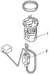
Fuel Pump Block — Description
Fig. 2.62. Fuel pump: 1 – fuel pump block; 2 – fuel level indicator sensor Since the vehicle uses a returnless fuel system, the fuel pump unit, except for the fuel gauge...
Fig. 2.62. Fuel pump: 1 – fuel pump block; 2 – fuel level indicator sensor Since the vehicle uses a returnless fuel system, the fuel pump unit, except for the fuel gauge...

Fuel and exhaust system components
Fig. 2.218. Components of the fuel and exhaust systems: 1 – air filter cover; 2 – air filter element; 3 – air filter housing; 4 – resonance chamber; 5 – VAD system...
Fig. 2.218. Components of the fuel and exhaust systems: 1 – air filter cover; 2 – air filter element; 3 – air filter housing; 4 – resonance chamber; 5 – VAD system...

Checking for fuel leaks
Disconnect the negative battery cable. Remove the fuel injectors together with the fuel distributor without disconnecting the fuel supply hose. Fig. 2.219. Fuel...
Disconnect the negative battery cable. Remove the fuel injectors together with the fuel distributor without disconnecting the fuel supply hose. Fig. 2.219. Fuel...

Performance Check
Note: If you do not have a special fuel injector tester, follow these steps: " Fuel Leak Test ", to check the serviceability of the fuel injector. Disconnect the...
Note: If you do not have a special fuel injector tester, follow these steps: " Fuel Leak Test ", to check the serviceability of the fuel injector. Disconnect the...

Checking the spray pattern
Fig. 2.222. Normal and abnormal fuel injector spray patterns Check the spray pattern of each fuel injector. If the spray pattern is not correct, replace the fuel...
Fig. 2.222. Normal and abnormal fuel injector spray patterns Check the spray pattern of each fuel injector. If the spray pattern is not correct, replace the fuel...

Removal and installation of the intake system (diesel)
Caution: The PCM is built into the air cleaner cover. Caution: Applying excessive force to the cover may damage the PCM. Caution: Be careful not to touch the PCM with...
Caution: The PCM is built into the air cleaner cover. Caution: Applying excessive force to the cover may damage the PCM. Caution: Be careful not to touch the PCM with...

Removal and installation the idle speed control valve (diesel)
Fig. 2.315. Idle speed controller Removal Remove the bottom cover. Remove the battery cover. Disconnect the negative cable from the battery. Remove the idle air control...
Fig. 2.315. Idle speed controller Removal Remove the bottom cover. Remove the battery cover. Disconnect the negative cable from the battery. Remove the idle air control...

Removal and installation the fuel control pedal (diesel)
Fig. 2.316. Accelerator pedal: 1 – fuel supply control pedal; 2 – throttle cable Removal Remove the fuel pedal. Disconnect the throttle cable. Installation Install in...
Fig. 2.316. Accelerator pedal: 1 – fuel supply control pedal; 2 – throttle cable Removal Remove the fuel pedal. Disconnect the throttle cable. Installation Install in...

Checking and adjusting the throttle cable (diesel)
Make sure the throttle valve closes completely. Fig. 2.317. Adjusting the throttle cable Move the throttle cable in directions A and B, and check whether the throttle...
Make sure the throttle valve closes completely. Fig. 2.317. Adjusting the throttle cable Move the throttle cable in directions A and B, and check whether the throttle...

Removal and installation of the fuel pump unit (diesel)
Fig. 2.321. Fuel pump: 1 – quick release connector; 2 – fuel pump cover; 3 – fuel pump block Removal Disconnect the negative cable from the battery. Remove the fuel...
Fig. 2.321. Fuel pump: 1 – quick release connector; 2 – fuel pump cover; 3 – fuel pump block Removal Disconnect the negative cable from the battery. Remove the fuel...
Checking for fuel leaks after installing the pump unit (diesel)
Before installing the fuel tank, check for fuel leaks by creating a pressure of +5.9 kPa in the fuel tank. Install the fuel tank. Set the car in motion and brake sharply...
Before installing the fuel tank, check for fuel leaks by creating a pressure of +5.9 kPa in the fuel tank. Install the fuel tank. Set the car in motion and brake sharply...

Removal and installation a fuel injector (diesel)
Removal Remove the battery cover. Disconnect the negative cable from the battery. Remove the air filter. Disconnect the fuel injector connector. Remove the quick release...
Removal Remove the battery cover. Disconnect the negative cable from the battery. Remove the air filter. Disconnect the fuel injector connector. Remove the quick release...

Intake system components (diesel)
Fig. 2.308. Components of the intake system of a car with a Z6 engine: 1 – air filter; 2 – electromagnetic valve of idle speed control; 3 – actuator of the air damper of...
Fig. 2.308. Components of the intake system of a car with a Z6 engine: 1 – air filter; 2 – electromagnetic valve of idle speed control; 3 – actuator of the air damper of...
This section is available on: russian, bulgarian, belarusian, ukrainian, serbian, croatian, romanian, polish, slovak, hungarian
More sections on repairs of other Mazda models
• Model «E» engine: Power and ignition system Mazda Familia 5 (1985-1989)
• Power unit: Power system (2.0 and 2.5) Mazda Capella 5 (1991-1997)
• Power unit: Fuel system Mazda6 GG (2002-2008)
• Power unit: Supply system Mazda CX-5KE (2012-2017)
• Power unit: Supply system Mazda 121 (3) (1996-2003)
• Model «E» engine: Power and ignition system Mazda Familia 5 (1985-1989)
• Power unit: Power system (2.0 and 2.5) Mazda Capella 5 (1991-1997)
• Power unit: Fuel system Mazda6 GG (2002-2008)
• Power unit: Supply system Mazda CX-5KE (2012-2017)
• Power unit: Supply system Mazda 121 (3) (1996-2003)
Link in different formats to this section
TEXTHTMLBB Code
- User manual
- Vehicle description
- Keys, locks and alarms
- Controls and instruments
- Air conditioning and heater
- Seat adjustment
- Security systems
- Driving and operation
- Faults en route
- Maintenance
- Power unit
- Engine device (gasoline)
- Engine repair (gasoline)
- Diesel engine (Z6)
- Lubrication system
- Cooling system
- Fuel system
- Exhaust system
- Engine electrical equipment
- Engine management system
- Transmission
- Clutch
- Mechanical gearbox
- Automatic gearbox
- Drive mechanism
- Chassis
- Suspension and wheels
- Steering
- Brake system
- Body
- Body elements
- Doors and windows
- Air conditioning and heater
- Electrical equipment
- Equipment and devices
- Power devices
- Lighting system
- Windshield wipers and washers
- Equipment checks