
Attention! The PCM is built into the air filter cover.
Attention! Applying excessive force to the cover may damage the PCM.
Attention! Be careful not to touch the PCM when removing and installing.
Attention! Removing the PCM from the air filter may damage it.
Attention! Do not remove the PCM from the air filter.
Removing
Remove the battery cover.
Disconnect the negative cable from the battery.
Remove the bottom cover.
Remove the connector cover and PCM connector.
Remove the air filter cover and remove the filter element.
Remove the air filter housing.
Remove the intake air duct cover and air duct.
Disconnect the air hose.
Remove the purge solenoid valve.
Drain the engine coolant.
Remove the throttle tube.
Disconnect the EGR pipe (from the intake manifold).
Disconnect the engine coolant hose from the engine coolant pipe.
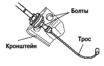
Pic. 2.310. Bracket of fastening of a cable of an accelerator
Remove the accelerator cable bracket from the intake manifold (pic. 2.310).
Remove the intake manifold.
Installation
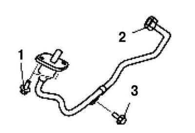
Pic. 2.311. Installation procedure for the exhaust gas recirculation mountings
Establish bolts and a nut of fastening of a pipe recirculation of the fulfilled gases in the order shown in drawing 2.311.
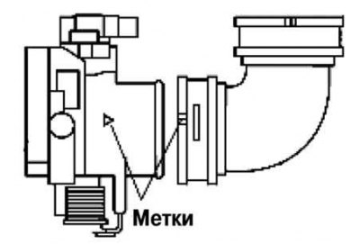
Pic. 2.312. Aligning the alignment marks on the throttle pipe and air hose
Align the marks on the throttle body and air hose (pic. 2.312).
Note. Before installing the air intake duct, make sure that the rubber fasteners on the battery bracket are in place.
Note. Use soapy water when installing the intake duct to the rubber mounts.
Make sure the two rubber mounts are installed on the battery bracket.
Install the intake duct into the rubber mounts.
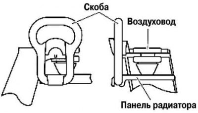
Pic. 2.313. Installing the Radiator Panel and Intake Air Duct
Using the bracket, secure the radiator frame panel and the intake system air duct as shown in Figure 2.313.
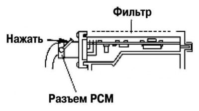
Pic. 2.314. Installing the PCM Connector
Insert the PCM connector fully into the air filter and press the lever until it clicks (pic. 2.314).
Install the remaining components in the reverse order of removal.