


Brake system of the car Mazda 3 (BK)

General information about the braking system
The vehicles described in this manual are equipped with a hydraulic brake system. The front brakes are disc brakes, the rear brakes are disc or drum brakes. All brakes...
The vehicles described in this manual are equipped with a hydraulic brake system. The front brakes are disc brakes, the rear brakes are disc or drum brakes. All brakes...
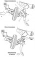
Trauma-safe brake pedal
The design of the safety brake pedal minimizes the amount of pedal backstroke. This ensures that the force of the impact on the lower part of the driver's body is...
The design of the safety brake pedal minimizes the amount of pedal backstroke. This ensures that the force of the impact on the lower part of the driver's body is...

Vacuum brake booster — description
The brake booster reduces the force on the brake pedal, making it easier to control the car. The brake booster uses a diaphragm, on both sides of which a vacuum is...
The brake booster reduces the force on the brake pedal, making it easier to control the car. The brake booster uses a diaphragm, on both sides of which a vacuum is...
Master Brake Cylinder — Description
The brake master cylinder is used on dual circuit brake systems. The front right and rear left brake mechanisms are actuated by the primary piston, and the front left...
The brake master cylinder is used on dual circuit brake systems. The front right and rear left brake mechanisms are actuated by the primary piston, and the front left...
Pressure regulator — description
The pressure regulator limits the output pressure to the rear brakes after the pressure has reached the maximum value in the master cylinder. The regulator is used when...
The pressure regulator limits the output pressure to the rear brakes after the pressure has reached the maximum value in the master cylinder. The regulator is used when...
Brake Fluid Level Sensor — Description
The brake fluid level sensor, located in the brake fluid reservoir, turns on the BRAKE indicator lamp when it detects a low fluid level. Once the level returns to...
The brake fluid level sensor, located in the brake fluid reservoir, turns on the BRAKE indicator lamp when it detects a low fluid level. Once the level returns to...
Anti-lock braking system (ABS)
Braking is most effective when the tire's grip on the road surface is at its maximum. During braking, the tire slides along the surface and the wheel's circumferential...
Braking is most effective when the tire's grip on the road surface is at its maximum. During braking, the tire slides along the surface and the wheel's circumferential...
Dynamic stability management
The DSC HU/CM hydraulic control mechanism and system control strategy are essentially the same as those of the previous 323 model, with the following exceptions: dSC...
The DSC HU/CM hydraulic control mechanism and system control strategy are essentially the same as those of the previous 323 model, with the following exceptions: dSC...
DSC indicator light
The DSC indicator lamp is located in the instrument cluster and notifies the driver that DSC is activated (the car is in sideways slip) or TCS activation (drive wheel...
The DSC indicator lamp is located in the instrument cluster and notifies the driver that DSC is activated (the car is in sideways slip) or TCS activation (drive wheel...
DSC switch, DSC off indicator lamp
The DSC switch is located on the instrument panel and switches off DSC when the corresponding button is pressed. The DSC off indicator lamp is located in the instrument...
The DSC switch is located on the instrument panel and switches off DSC when the corresponding button is pressed. The DSC off indicator lamp is located in the instrument...

Integrated Dynamic Stability Control Sensor
The yaw rate sensor and lateral G-force sensor are combined. The combined sensor is mounted on the left side of the parking brake lever (left hand drive models) or on...
The yaw rate sensor and lateral G-force sensor are combined. The combined sensor is mounted on the left side of the parking brake lever (left hand drive models) or on...

DSC HU/CM Dynamic Stability Control Unit
A compact and lightweight integrated DSC HU/CM unit with increased reliability is used. The DSC HU/CM unit calculates the input signals of all sensors and controls the...
A compact and lightweight integrated DSC HU/CM unit with increased reliability is used. The DSC HU/CM unit calculates the input signals of all sensors and controls the...

Emergency Brake Control
During emergency braking, the DSC HU/CM increases the brake fluid pressure by increasing the pressure in the master cylinder, so that greater braking force is achieved...
During emergency braking, the DSC HU/CM increases the brake fluid pressure by increasing the pressure in the master cylinder, so that greater braking force is achieved...
Controller Area Network (CAN)
Anti-lock braking system (ABS/TCS) and DSC HU/CM transmit/receive information via CAN. They transmit information: about the path traveled; about wheel speed; from the...
Anti-lock braking system (ABS/TCS) and DSC HU/CM transmit/receive information via CAN. They transmit information: about the path traveled; about wheel speed; from the...

On-board diagnostics of the brake system
The operation of the on-board diagnostics system of the anti-lock braking system (ABS/TCS) or DSC is essentially carried over from the previous model 323 (BJ), with the...
The operation of the on-board diagnostics system of the anti-lock braking system (ABS/TCS) or DSC is essentially carried over from the previous model 323 (BJ), with the...
Checking and adjusting the brake system components
Check the brakes on a dry and level road, at different vehicle speeds with light and strong pressure on the brake pedal, avoiding locking the brakes and slipping the...
Check the brakes on a dry and level road, at different vehicle speeds with light and strong pressure on the brake pedal, avoiding locking the brakes and slipping the...
Checking the brake fluid level in the hydraulic reservoir of the service brake system
The brake fluid reservoir is located in the engine compartment. The reservoir has a transparent body, so the brake fluid level can be monitored from the outside. The...
The brake fluid reservoir is located in the engine compartment. The reservoir has a transparent body, so the brake fluid level can be monitored from the outside. The...

Bleeding the brake system
Note: The brake hydraulic system must be bled whenever the brake lines are disconnected. If a hydraulic line is disconnected from a master cylinder, bleeding should...
Note: The brake hydraulic system must be bled whenever the brake lines are disconnected. If a hydraulic line is disconnected from a master cylinder, bleeding should...

Checking the vacuum hose check valve (brake booster)
Remove the clamps and vacuum hose. Fig. 6.10. Check valve testing diagram Apply vacuum and pressure alternately to the engine side vacuum hose and make sure that air can...
Remove the clamps and vacuum hose. Fig. 6.10. Check valve testing diagram Apply vacuum and pressure alternately to the engine side vacuum hose and make sure that air can...

Removal and installation a vacuum hose (brake booster)
Fig. 6.11. Disconnecting the vacuum hose connector Disconnect the vacuum hose connector from the brake booster by pressing on the tabs of the vacuum hose connector (Fig....
Fig. 6.11. Disconnecting the vacuum hose connector Disconnect the vacuum hose connector from the brake booster by pressing on the tabs of the vacuum hose connector (Fig....

Checking the brake pedal
Checking the brake pedal height Make sure the distance from the floor mat to the center of the top surface of the pedal support area is within the specified range. Pedal...
Checking the brake pedal height Make sure the distance from the floor mat to the center of the top surface of the pedal support area is within the specified range. Pedal...
Removal and installation the brake pedal
Removal Caution! The gap between the brake light switch and the brake pedal is adjusted automatically when the brake light switch is inserted into the hole on the brake...
Removal Caution! The gap between the brake light switch and the brake pedal is adjusted automatically when the brake light switch is inserted into the hole on the brake...

Removal and installation the master brake cylinder
Fig. 6.22. Dismantling components of the master brake cylinder: 1 – brake fluid level sensor connector; 2 – brake line; 3 – hose (models with manual transmission); 4 –...
Fig. 6.22. Dismantling components of the master brake cylinder: 1 – brake fluid level sensor connector; 2 – brake line; 3 – hose (models with manual transmission); 4 –...

Checking the liquid level sensor
Disconnect the negative battery cable. Disconnect the sensor connector. Fig. 6.29. Liquid level sensor test diagram Check the continuity of the circuit between the...
Disconnect the negative battery cable. Disconnect the sensor connector. Fig. 6.29. Liquid level sensor test diagram Check the continuity of the circuit between the...

Removal and installation the brake booster
Fig. 6.30. Components of the brake booster: 1 – brake line; 2 – vacuum hose; 3 – connector; 4 – brake line; 5 – hinge axis; 6 – brake pedal assembly; 7 – brake booster;...
Fig. 6.30. Components of the brake booster: 1 – brake line; 2 – vacuum hose; 3 – connector; 4 – brake line; 5 – hinge axis; 6 – brake pedal assembly; 7 – brake booster;...

Checking the brake booster
The brake booster, located on the firewall, operates using the vacuum in the intake manifold and atmospheric pressure. After completing each operation that involved...
The brake booster, located on the firewall, operates using the vacuum in the intake manifold and atmospheric pressure. After completing each operation that involved...

Disassembly and assembly of the master cylinder
Caution! If the master cylinder housing is damaged, replace the master cylinder assembly. When clamping the master cylinder in a vice, clamp only the protrusion of the...
Caution! If the master cylinder housing is damaged, replace the master cylinder assembly. When clamping the master cylinder in a vice, clamp only the protrusion of the...

Removal and installation the front brake disc
Fig. 6.38. Front brake mechanism: 1 – flexible hose; 2 – lid; 3 – guide pin; 4 – support; 5 – M-shaped spring; 6 – brake disc pad; 7 – guide plate; 8 – support; 9 –...
Fig. 6.38. Front brake mechanism: 1 – flexible hose; 2 – lid; 3 – guide pin; 4 – support; 5 – M-shaped spring; 6 – brake disc pad; 7 – guide plate; 8 – support; 9 –...

Checking the brake disc and brake components
Check the inner cylinder walls for corrosion, wear and damage. Replace the cylinder body if necessary. Remove minor defects caused by corrosion or foreign particles by...
Check the inner cylinder walls for corrosion, wear and damage. Replace the cylinder body if necessary. Remove minor defects caused by corrosion or foreign particles by...

Replacing the front brake pads
When the cylinder body is open, do not press the brake pedal, otherwise the piston will jump out. Do not damage the piston dust boot and do not allow oil to get on the...
When the cylinder body is open, do not press the brake pedal, otherwise the piston will jump out. Do not damage the piston dust boot and do not allow oil to get on the...

Removal and installation the rear disc brake mechanism
Fig. 6.51. Components of the rear brake mechanism: 1 – parking brake cable; 2 – brake line; 3 – clamp; 4 – clamp; 5 – lid; 6 – bolt; 7 – caliper, brake hose; 8 – case; 9...
Fig. 6.51. Components of the rear brake mechanism: 1 – parking brake cable; 2 – brake line; 3 – clamp; 4 – clamp; 5 – lid; 6 – bolt; 7 – caliper, brake hose; 8 – case; 9...

Checking the parking brake system
Fig. 6.56. Parking brake system circuit: 1 – Parking brake switch; 2 – adjusting nut; 3 – parking brake lever; 4 – clamp; 5 – parking brake system cables Pull the...
Fig. 6.56. Parking brake system circuit: 1 – Parking brake switch; 2 – adjusting nut; 3 – parking brake lever; 4 – clamp; 5 – parking brake system cables Pull the...

Adjusting the parking brake system
Start the engine and press the brake pedal several times. Stop the engine. Remove the ashtray behind the center console. Fig. 6.57. Adjusting nut of the parking brake...
Start the engine and press the brake pedal several times. Stop the engine. Remove the ashtray behind the center console. Fig. 6.57. Adjusting nut of the parking brake...

Removal, checking and installation the rear ABS wheel speed sensor
Fig. 6.58. Rear ABS wheel speed sensor: 1 – connector; 2 – mounting bracket bolts; 3 – sensor Checking the gap between the wheel speed sensor and the sensor rotor Fig....
Fig. 6.58. Rear ABS wheel speed sensor: 1 – connector; 2 – mounting bracket bolts; 3 – sensor Checking the gap between the wheel speed sensor and the sensor rotor Fig....

Removal and installation of the hydraulic unit of the anti-lock braking system
Attention! The internal components of the hydraulic unit of the anti-lock braking system can be damaged if the unit falls on a hard surface. Take care not to drop the...
Attention! The internal components of the hydraulic unit of the anti-lock braking system can be damaged if the unit falls on a hard surface. Take care not to drop the...

Technical characteristics of brake system components
Table 6.1. Technical characteristics of brake system components Table 6.6. Brake system working fluids
Table 6.1. Technical characteristics of brake system components Table 6.6. Brake system working fluids

Purpose and functions of the DSC system
Table 6.2. Purpose and functions of the DSC system Table 6.3. Operation of the DSC indicator lamp Table 6.4. Functions of the DSC HU/CM dynamic stability control unit
Table 6.2. Purpose and functions of the DSC system Table 6.3. Operation of the DSC indicator lamp Table 6.4. Functions of the DSC HU/CM dynamic stability control unit
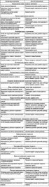
Possible malfunctions of the brake system, their causes and methods of elimination
Table 6.5. Possible malfunctions of the brake system, their causes and methods of elimination
Table 6.5. Possible malfunctions of the brake system, their causes and methods of elimination
This section is available on: russian, bulgarian, belarusian, ukrainian, serbian, croatian, romanian, polish, slovak, hungarian
More sections on repairs of other Mazda models
• Chassis: Brake system Mazda Familia 5 (1985-1989)
• Chassis: Brake system Mazda Capella 6 (1997-2005, petrol)
• Chassis: Brake system Mazda6 GG (2002-2008)
• Chassis: Brake system Mazda CX-5KE (2012-2017)
• Chassis: Brake system Mazda BT-50 (1) (2006-2011)
• Chassis: Brake system Mazda Familia 5 (1985-1989)
• Chassis: Brake system Mazda Capella 6 (1997-2005, petrol)
• Chassis: Brake system Mazda6 GG (2002-2008)
• Chassis: Brake system Mazda CX-5KE (2012-2017)
• Chassis: Brake system Mazda BT-50 (1) (2006-2011)
Link in different formats to this section
TEXTHTMLBB Code
- User manual
- Vehicle description
- Keys, locks and alarms
- Controls and instruments
- Air conditioning and heater
- Seat adjustment
- Security systems
- Driving and operation
- Faults en route
- Maintenance
- Power unit
- Engine device (gasoline)
- Engine repair (gasoline)
- Diesel engine (Z6)
- Lubrication system
- Cooling system
- Fuel system
- Exhaust system
- Engine electrical equipment
- Engine management system
- Transmission
- Clutch
- Mechanical gearbox
- Automatic gearbox
- Drive mechanism
- Chassis
- Suspension and wheels
- Steering
- Brake system
- Body
- Body elements
- Doors and windows
- Air conditioning and heater
- Electrical equipment
- Equipment and devices
- Power devices
- Lighting system
- Windshield wipers and washers
- Equipment checks