


- diagnostic codes, PID data monitor functions and active command functions have been modified;
- removed TBS pin of DLC connector;
- the use of WDS or equivalent with anti-lock braking system (ABS/TCS) or DSC HU/CM allows for four-digit display of diagnostic codes and active assignment of command modes, which improves maintainability.
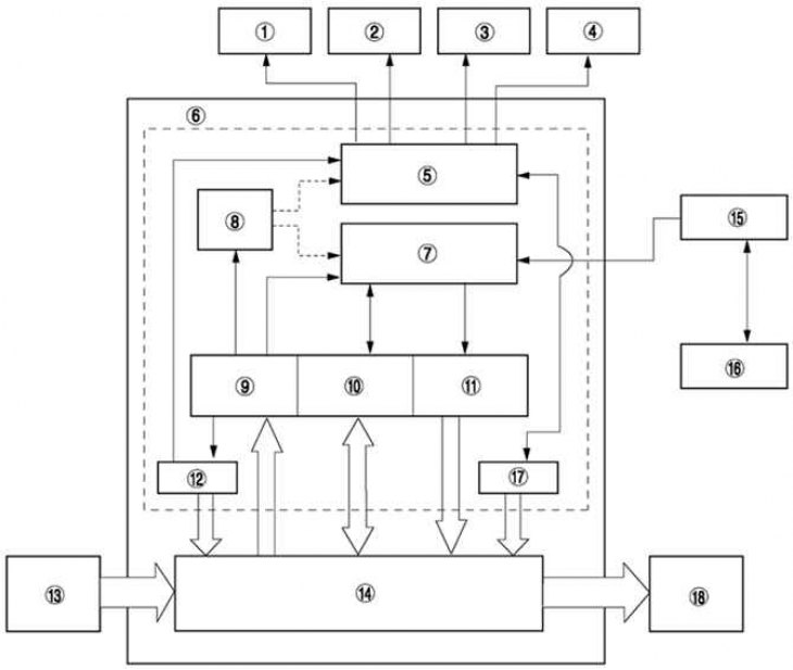
Fig. 6.8. Block diagram of the on-board diagnostics system of the Mazda 3: 1 – TCS (DSC) system control lamp; 2 – TCS (DSC) system deactivation indicator lamp; 3 – Anti-lock braking system warning light; 4 – brake system warning light; 5 – malfunction display function; 6 – On-board diagnostics function; 7 – Consistent communication; 8 – memory function; 9 – Fault detection function; 10 – data control function; 11 – Active command function; 12 – reliability function; 13 – data input device; 14 – normal control area; 15 – DLC connector 2; 16 – WDS or similar; 17 – hydraulic elements testing function; 18 – output device