


Gasoline Engine Device Mazda 3 (BK)

General description of engines of models L8, LF and L3
Fig. 2.1. Diagram of dynamic characteristics of Mazda 3 engines The Mazda 3 is equipped with modern new generation engines with improved dynamic and maintainability...
Fig. 2.1. Diagram of dynamic characteristics of Mazda 3 engines The Mazda 3 is equipped with modern new generation engines with improved dynamic and maintainability...

Cylinder Head Cover — Description
Fig. 2.3. Cylinder head cover: 1 – camshaft position sensor (CMP); 2 – Oil control valve (OCV) mounting hole (l3 engine); 3 – oil filler cap The cylinder head cover is...
Fig. 2.3. Cylinder head cover: 1 – camshaft position sensor (CMP); 2 – Oil control valve (OCV) mounting hole (l3 engine); 3 – oil filler cap The cylinder head cover is...

Cylinder head — description
Fig. 2.4. Cylinder head: 1 – cylinder head mounting bolt; 2 – release side; 3 – inlet side; 4 – front part of the engine; 5 – angle between two valves; 6 – inlet...
Fig. 2.4. Cylinder head: 1 – cylinder head mounting bolt; 2 – release side; 3 – inlet side; 4 – front part of the engine; 5 – angle between two valves; 6 – inlet...

Cylinder Head Gasket — Description
Fig. 2.5. Cylinder head gasket: 1 – plate; 2 – gasket The cylinder head gasket is metal and has a two-layer structure (Fig. 2.5).
Fig. 2.5. Cylinder head gasket: 1 – plate; 2 – gasket The cylinder head gasket is metal and has a two-layer structure (Fig. 2.5).

Cylinder Block — Description
The technological feature of the new cylinder block is that it is cast from an aluminum alloy with cast-iron cylinder liners installed inside the housing. This improves...
The technological feature of the new cylinder block is that it is cast from an aluminum alloy with cast-iron cylinder liners installed inside the housing. This improves...

Crankshaft and main bearing — description
Fig. 2.8. Crankshafts of engines of models L8, LF and L3: 1 – drive gear The crankshafts of the L8 and LF engines are cast iron, 5-bearing, with 4 counterweights. The...
Fig. 2.8. Crankshafts of engines of models L8, LF and L3: 1 – drive gear The crankshafts of the L8 and LF engines are cast iron, 5-bearing, with 4 counterweights. The...

Balancing unit — description
Fig. 2.11. Balancing block: 1 – cassette type balancing unit; 2 – balancing shaft A removable cassette type balancing unit is used in L3 engines to reduce engine...
Fig. 2.11. Balancing block: 1 – cassette type balancing unit; 2 – balancing shaft A removable cassette type balancing unit is used in L3 engines to reduce engine...

The principle of operation of the balancing unit
Fig. 2.12. Operating principle of the balancing unit: 1 – adjusting gasket; 2 – crankshaft; 3 – front part of the engine; 4 – balancing unit housing; 5 – counterweights;...
Fig. 2.12. Operating principle of the balancing unit: 1 – adjusting gasket; 2 – crankshaft; 3 – front part of the engine; 4 – balancing unit housing; 5 – counterweights;...

Crankshaft torsional vibration damper
Fig. 2.14. Crankshaft torsional vibration damper: 1 - vertical projection; 2 – section; 3 – toothed wheel of crankshaft pulley; 4 – pulley mounting hole; 5 – torsional...
Fig. 2.14. Crankshaft torsional vibration damper: 1 - vertical projection; 2 – section; 3 – toothed wheel of crankshaft pulley; 4 – pulley mounting hole; 5 – torsional...

Front Engine Cover — Description
Fig. 2.15. Front engine cover: 1 - vertical projection; 2 – technological hole for fixing the tensioner lever; 3 – technological hole for unlocking the chain tensioner;...
Fig. 2.15. Front engine cover: 1 - vertical projection; 2 – technological hole for fixing the tensioner lever; 3 – technological hole for unlocking the chain tensioner;...

Piston — Description
The pistons are made of heat-resistant and highly thermally conductive aluminum alloy, the piston skirt is coated with graphite to reduce friction. Fig. 2.16. Piston: 1...
The pistons are made of heat-resistant and highly thermally conductive aluminum alloy, the piston skirt is coated with graphite to reduce friction. Fig. 2.16. Piston: 1...

Piston rings and piston pin — description
Fig. 2.17. Piston rings and piston pin: 1 – section of the upper ring; 2 – section of the second ring; 3 – section of oil scraper ring; 4 – side rings; 5 – expander The...
Fig. 2.17. Piston rings and piston pin: 1 – section of the upper ring; 2 – section of the second ring; 3 – section of oil scraper ring; 4 – side rings; 5 – expander The...

Connecting rod and connecting rod bearing — description
Fig. 2.18. Connecting rod and connecting rod bearing: 1 - extension; 2 – connecting rod; 3 – connector surface; 4 – connecting rod cover; 5 – connecting rod bearing The...
Fig. 2.18. Connecting rod and connecting rod bearing: 1 - extension; 2 – connecting rod; 3 – connector surface; 4 – connecting rod cover; 5 – connecting rod bearing The...

Valve mechanism — general information
Fig. 2.20. Valve mechanism of Mazda 3 engines: 1 – camshaft; 2 - timing gear drive chain; 3 – camshaft sprocket; 4 – tensioner lever; 5 – chain tensioner; 6 – crankshaft...
Fig. 2.20. Valve mechanism of Mazda 3 engines: 1 – camshaft; 2 - timing gear drive chain; 3 – camshaft sprocket; 4 – tensioner lever; 5 – chain tensioner; 6 – crankshaft...

Camshaft — Description
The camshaft position (CMP) detection unit or sensor, which is integrated with the camshaft, is located in the intake camshaft on L8 and LF model engines. The camshaft...
The camshaft position (CMP) detection unit or sensor, which is integrated with the camshaft, is located in the intake camshaft on L8 and LF model engines. The camshaft...

Camshaft Sprocket — Description
Fig. 2.23. Camshaft sprocket: 1 – camshaft sprocket; 2 – actuator for changing valve timing The design uses a camshaft sprocket made of a high-rigidity alloy, hardened...
Fig. 2.23. Camshaft sprocket: 1 – camshaft sprocket; 2 – actuator for changing valve timing The design uses a camshaft sprocket made of a high-rigidity alloy, hardened...

Crankshaft Sprocket — Description
Fig. 2.24. Crankshaft sprocket: 1 – oil pump drive sprocket; 2 – timing mechanism drive sprocket; 3 – front part of the engine; 4 – outer diameter; 5 – tooth width The...
Fig. 2.24. Crankshaft sprocket: 1 – oil pump drive sprocket; 2 – timing mechanism drive sprocket; 3 – front part of the engine; 4 – outer diameter; 5 – tooth width The...

Timing Chain — Description
Fig. 2.25. Timing chain: 1 – camshaft sprocket; 2 – tensioner lever; 3 – chain tensioner; 4 – chain guide; 5 – crankshaft sprocket; 6 -timing mechanism drive chain; 7 –...
Fig. 2.25. Timing chain: 1 – camshaft sprocket; 2 – tensioner lever; 3 – chain tensioner; 4 – chain guide; 5 – crankshaft sprocket; 6 -timing mechanism drive chain; 7 –...

Timing chain tensioner
Fig. 2.26. Timing chain tensioner: 1 – ratchet mechanism hole; 2 – oil supply hole; 3 – check valve; 4 – piston spring; 5 – piston; 6 – toothed rack; 7 – ratchet; 8 –...
Fig. 2.26. Timing chain tensioner: 1 – ratchet mechanism hole; 2 – oil supply hole; 3 – check valve; 4 – piston spring; 5 – piston; 6 – toothed rack; 7 – ratchet; 8 –...
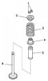
Valve, valve spring, valve stem seal, valve guide
Fig. 2.27. Valve components: 1 – valve cracker; 2 – upper valve spring plate; 3 – valve spring; 4 – oil deflector cap; 5 – valve guide bushing; 6 – valve The valves are...
Fig. 2.27. Valve components: 1 – valve cracker; 2 – upper valve spring plate; 3 – valve spring; 4 – oil deflector cap; 5 – valve guide bushing; 6 – valve The valves are...

Valve tappet — description
Fig. 2.28. Valve mechanism operation diagram: 1 – valve tappet; 2 – camshaft; 3 – valve tappet section; 4 – contact surface of the cam contour; 5 – valve stem contact...
Fig. 2.28. Valve mechanism operation diagram: 1 – valve tappet; 2 – camshaft; 3 – valve tappet section; 4 – contact surface of the cam contour; 5 – valve stem contact...

Variable valve timing mechanism
Fig. 2.29. Diagram of the valve timing mechanism: 1 – torque; 2 – engine speed; 3 – low and medium speed engine; 4 – high speed engine; 5 – engine with variable valve...
Fig. 2.29. Diagram of the valve timing mechanism: 1 – torque; 2 – engine speed; 3 – low and medium speed engine; 4 – high speed engine; 5 – engine with variable valve...

Variable valve timing system
The variable valve timing system continuously modifies the phases of the variable valve timing actuator and the intake camshaft under the action of hydraulic pressure,...
The variable valve timing system continuously modifies the phases of the variable valve timing actuator and the intake camshaft under the action of hydraulic pressure,...

Structural diagram of the valve timing mechanism
Fig. 2.31. Structural diagram of the valve timing mechanism: 1 – crankshaft position sensor; 2 – camshaft position sensor; 3 – PCM block; 4 – Oil control valve (OCV); 5...
Fig. 2.31. Structural diagram of the valve timing mechanism: 1 – crankshaft position sensor; 2 – camshaft position sensor; 3 – PCM block; 4 – Oil control valve (OCV); 5...

Main characteristics of the variable valve timing mechanism
The variable valve timing actuator has two hydraulic chambers: a valve advance chamber and a valve retard chamber. The chambers are located between the integrated...
The variable valve timing actuator has two hydraulic chambers: a valve advance chamber and a valve retard chamber. The chambers are located between the integrated...

Design of the variable valve timing mechanism
Fig. 2.36. Design of the variable valve timing mechanism: 1 – camshaft sprocket; 2 – body; 3 – rotor; 4 – pin; 5 – seal; 6 – lid; 7 – groove The variable valve timing...
Fig. 2.36. Design of the variable valve timing mechanism: 1 – camshaft sprocket; 2 – body; 3 – rotor; 4 – pin; 5 – seal; 6 – lid; 7 – groove The variable valve timing...

Oil Control Valve (OCV)
Fig. 2.37. Design of the oil control valve (OCV): 1 – spool valve; 2 – spiral; 3 – plunger; 4 – return spring The oil control valve (OCV) consists of a spool valve that...
Fig. 2.37. Design of the oil control valve (OCV): 1 – spool valve; 2 – spiral; 3 – plunger; 4 – return spring The oil control valve (OCV) consists of a spool valve that...

Specifications of engines and its components
Table 2.1. Technical characteristics of engines Table 2.2. Types of main bearing shells, mm Table 2.3. Piston characteristics Table 2.4. Connecting rod bearing shell...
Table 2.1. Technical characteristics of engines Table 2.2. Types of main bearing shells, mm Table 2.3. Piston characteristics Table 2.4. Connecting rod bearing shell...
This section is available on: russian, bulgarian, belarusian, ukrainian, serbian, croatian, romanian, polish, slovak, hungarian
More sections on repairs of other Mazda models
• Model «E» engine: Engine repair Mazda Familia 5 (1985-1989)
• Power unit: Engine in car Mazda Capella 3 (1982-1992, petrol)
• Power unit: Engine device Mazda6 GG (2002-2008)
• Power unit: Engine repair (diesel) Mazda BT-50 (1) (2006-2011)
• Model «E» engine: Engine repair Mazda Familia 5 (1985-1989)
• Power unit: Engine in car Mazda Capella 3 (1982-1992, petrol)
• Power unit: Engine device Mazda6 GG (2002-2008)
• Power unit: Engine repair (diesel) Mazda BT-50 (1) (2006-2011)
Link in different formats to this section
TEXTHTMLBB Code
- User manual
- Vehicle description
- Keys, locks and alarms
- Controls and instruments
- Air conditioning and heater
- Seat adjustment
- Security systems
- Driving and operation
- Faults en route
- Maintenance
- Power unit
- Engine device (gasoline)
- Engine repair (gasoline)
- Diesel engine (Z6)
- Lubrication system
- Cooling system
- Fuel system
- Exhaust system
- Engine electrical equipment
- Engine management system
- Transmission
- Clutch
- Mechanical gearbox
- Automatic gearbox
- Drive mechanism
- Chassis
- Suspension and wheels
- Steering
- Brake system
- Body
- Body elements
- Doors and windows
- Air conditioning and heater
- Electrical equipment
- Equipment and devices
- Power devices
- Lighting system
- Windshield wipers and washers
- Equipment checks