Table 2.1. Engine Specifications
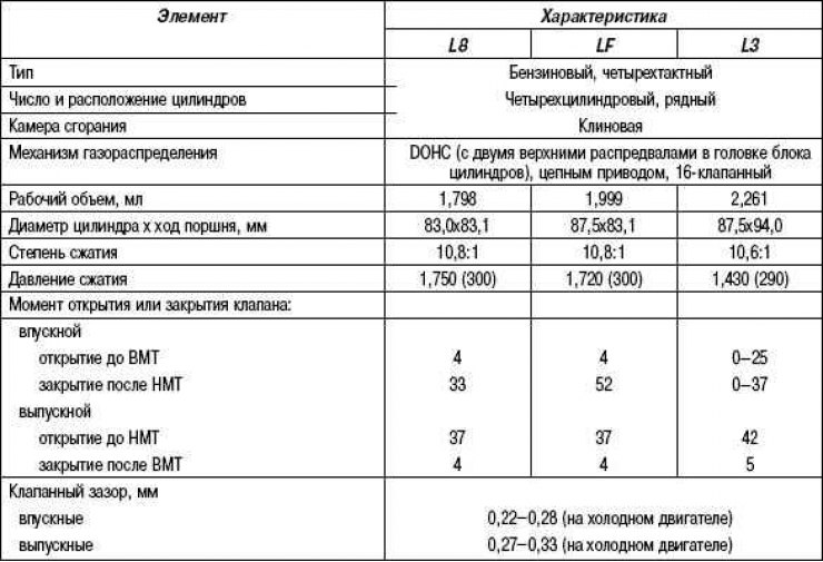
Table 2.2. Types of liners of main bearings, mm
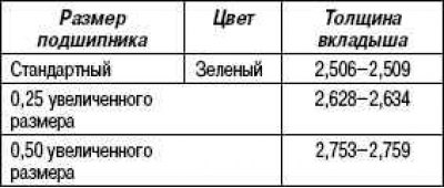
Table 2.3. Piston characteristics
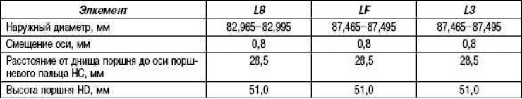
Table 2.4. Types of connecting rod bearing shells (mm)
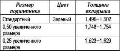
Table 2.5. Drive belt specifications
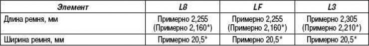
* vehicles without air conditioning
Table 2.6. Camshaft specifications
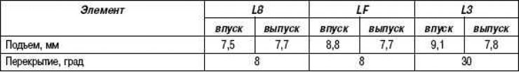
Table 2.7. Characteristics of the timing gear drive sprocket

Table 2.8. Characteristics of the oil pump drive sprocket
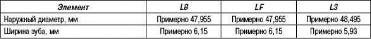
Table 2.9. Characteristics of the timing chain drive
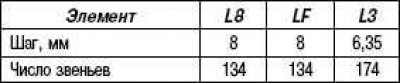
Table 2.10. Valve specifications
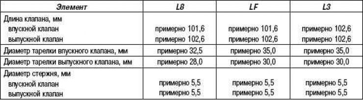
Table 2.11. Valve lifter specifications
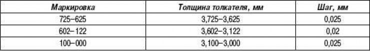
Table 2.12. Elements and their functions
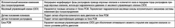
Table 2.13. Specifications of the lubrication system

Table 2.14. Recommended engine oil
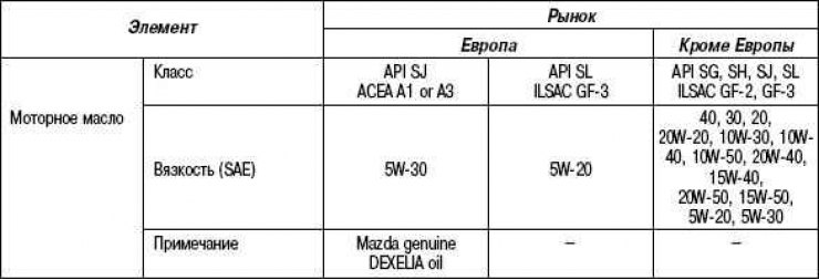
Table 2.15. Oil pump specifications
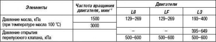
Table 2.16. Oil filter specifications
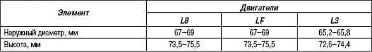
Table 2.17. Specifications of the cooling system
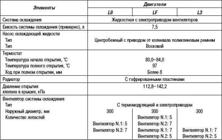
Table 2.18. Characteristics of the cooling fan, fan motor
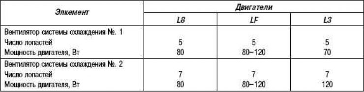
Table 2.19. Fuel System Specifications
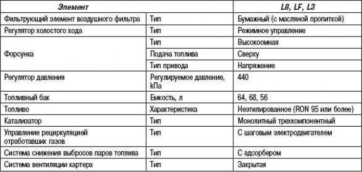
Table 2.20. Specifications of the intake system
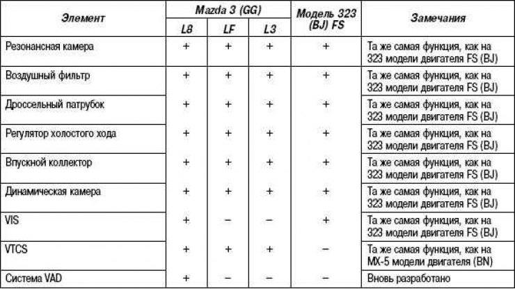
Table 2.21. Technical systems of electric equipment of engines
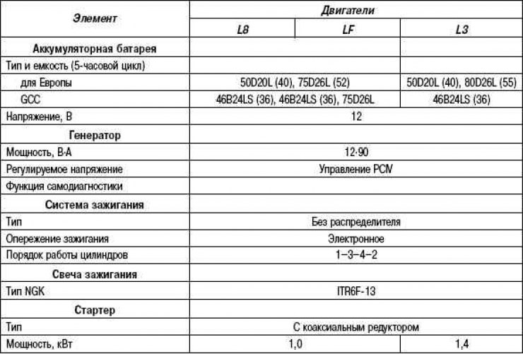
Table 2.22. Pin assignment
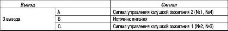
Table 2.23. Adjusting shims of the balancing block, engines with an installed mechanism for changing the valve timing
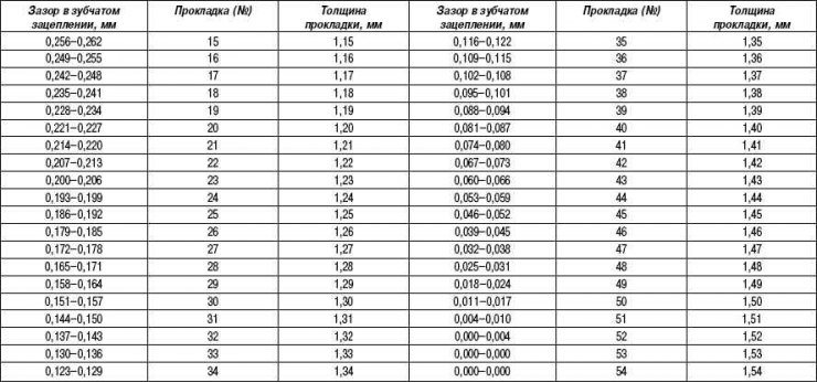
Table 2.24. Technical data of the mechanical part of engines of models L8, LF, L3
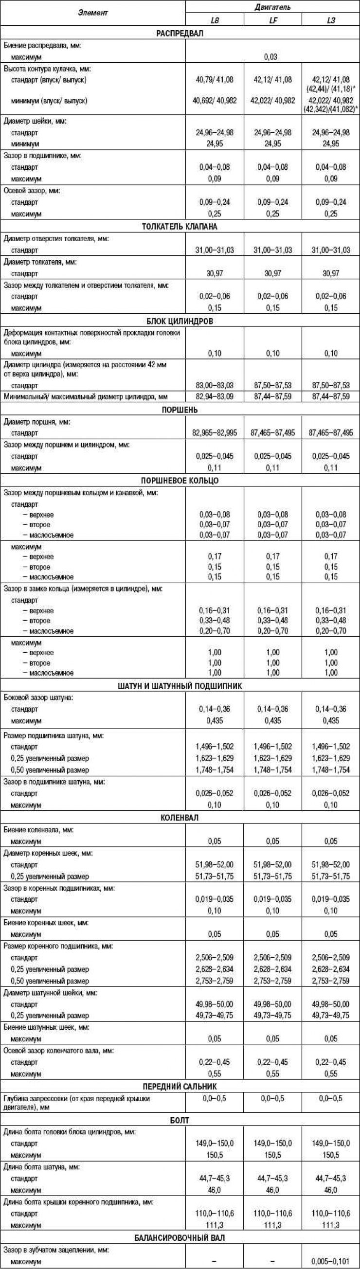
* with variable valve timing mechanism
Table 2.25. Oil filling volume (approximate amount), l
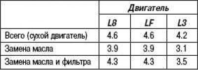
Table 2.26. Target engine speed
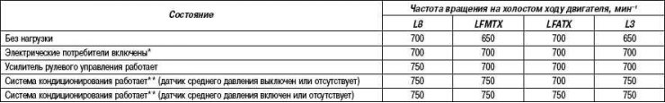
* Headlights on, blower switch set to any speed other than 1st, cooling fan running, and rear defroster on.
** Air conditioning switch and fan switch are in the on position.
Table 2.27. Conditions for turning off the air conditioning system
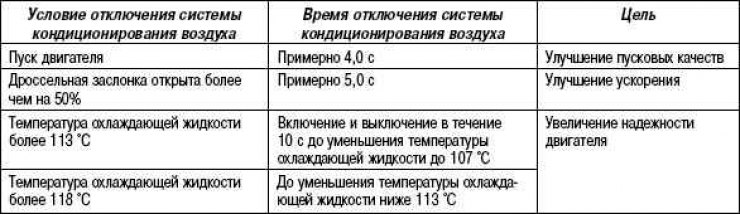
Table 2.28. Electric fan control for L8, LF engines (hot area) and L3 engine
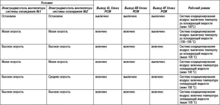
Table 2.29. Monitoring system
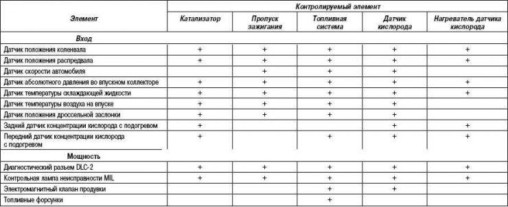
Table 2.30. Emission related diagnostic codes (diagnostic code) (mode 03)
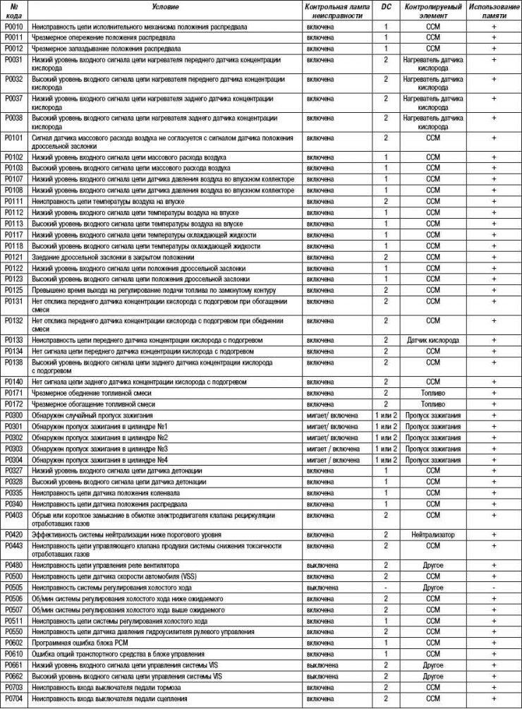
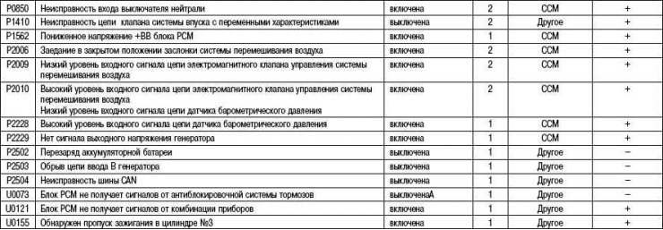
+ Applicable
- Not applicable
Table 2.31. Sending Periodic Monitoring System Diagnostic Results (mode 06)
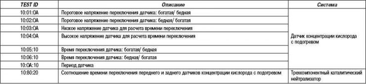
Table 2.32. Specifications of the Z6 engine
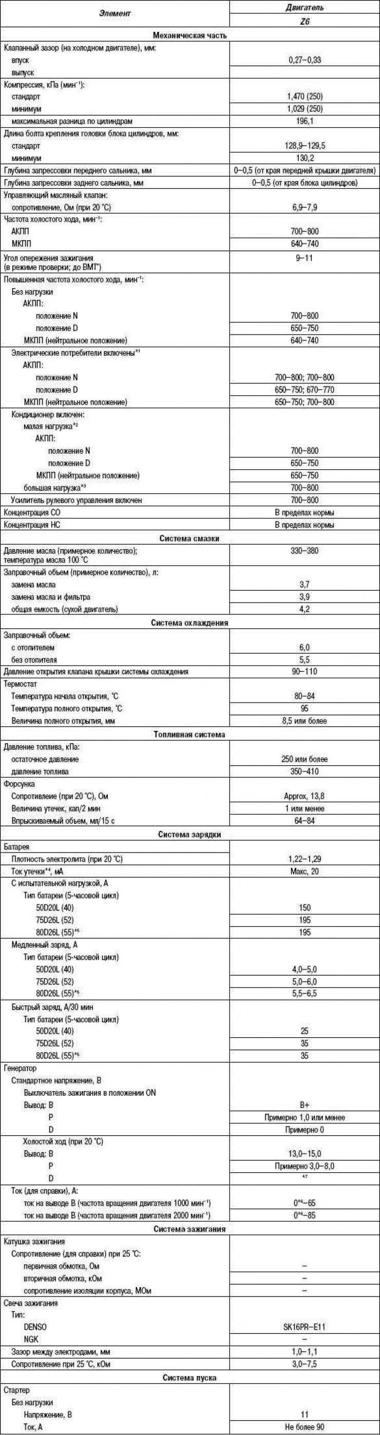
*1 Generator that generates the current value.
*2 Refrigerant pressure sensor (average) switched off.
*3 Refrigerant pressure sensor (average) included.
*4 Leakage current - steady state current (for audio unit, clock, PCM unit, etc.), when the ignition switch is in the off position and the ignition key is removed from the lock.
*5 For hot area.
*6 The lower limit must be greater than 0 A.
*7 Turn on the following electrical consumers and check that the voltage rises:
– headlights;
– electric motor of the fan of a heater;
– a heater of back glass.
Table 2.33. Recommended engine oil
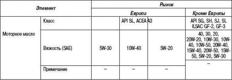
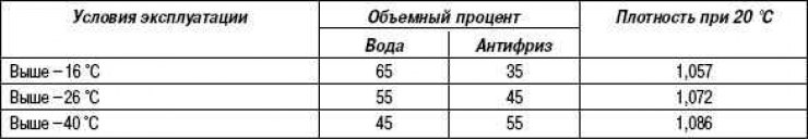
Table 2.34. Antifreeze concentration