


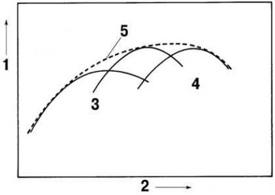
Fig. 2.29. Diagram of the valve timing mechanism: 1 – torque; 2 – engine speed; 3 – low and medium speed engine; 4 – high speed engine; 5 – engine with variable valve timing mechanism
The variable valve timing mechanism ensures the optimum valve opening and closing moment according to engine operating conditions by continuously changing the phases of the intake valve camshaft and crankshaft (Fig. 2.29).
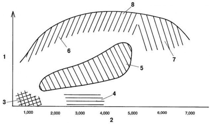
Fig. 2.30. Diagram of changes in valve timing for different engine operating ranges: 1 – load; 2 – engine speed; 3 – idle speed range; 4 – low load range; 5 – medium load range; 6 – range of high loads of low and medium speeds; 7 – high load and high speed range; 8 – full load operation
(Original material on the website mazbook.ru)