


Contents: Front toothed belt ⇓ Rear toothed belt ⇓
The valve timing must be adjusted after repair work that involved removing the timing belt or disassembling the engine. When checking the valve timing, all operations must be performed except replacing the timing belt.
Caution! Disconnecting the negative battery cable will erase the memory of electronic memory devices, such as engine fault memory or radio codes.
Front toothed belt
Removal
Disconnect the cable from the negative battery terminal.
Raise the vehicle and remove the right front wheel.
Remove the lower engine cover in the right wheel arch.
Remove the V-belt.
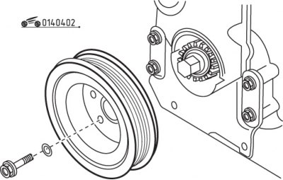
Figure 4.2. Removing the pulley from the crankshaft
Secure the engine crankshaft from turning and unscrew the crankshaft belt pulley mounting bolts (figure 4.2).
To lock the engine, engage 5th gear and have the assistant press the brake pedal.
Remove the glow plugs. To turn the engine crankshaft, apply the parking brake and move the gear lever to neutral. Using a ratchet and socket, turn the crankshaft from the right wheel arch side.
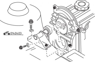
Figure 4.3. Removing the engine damper
Remove the bolts and the engine damper (figure 4.3).
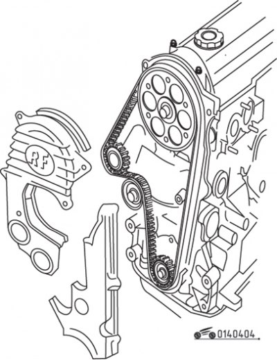
Figure 4.4. Removing the right and left timing belt covers
Remove the right and left timing belt covers (figure 4.4).
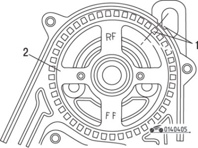
Figure 4.5. Alignment of mark (1) on the toothed belt pulley with mark (2) on the rear casing when setting the piston of the first cylinder to TDC in the compression stroke
Set the piston of the first cylinder to TDC in the compression stroke. To do this, turn the engine crankshaft until the mark on the camshaft pulley aligns with the mark on the rear timing belt cover (figure 4.5).
Caution! Never turn the crankshaft using the camshaft pulley via the belt drive.
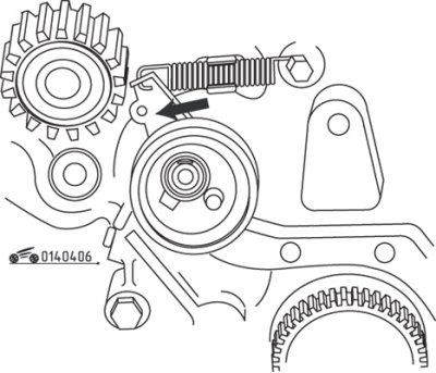
Figure 4.6. Direction of deflection of the tension roller to loosen the toothed belt tension
Loosen the tension roller mounting bolt and use a screwdriver to push the tension roller away from the timing belt (figure 4.6). After loosening the timing belt tension, tighten the tension roller mounting bolt again.
Use chalk, marker or paint to mark the direction of rotation of the timing belt. If the timing belt rotates in the opposite direction during installation, it will be damaged. The engine pulleys rotate clockwise.
Remove the timing belt. After removing the timing belt, do not turn the pulleys.
If it is necessary to turn the camshaft, first set all pistons to the middle of their stroke. To do this, use chalk to make a mark on the top of the crankshaft pulley, with the crankshaft in the TDC position of the first cylinder, then turn the crankshaft pulley 1/4 turn (90°) to the left or right. Now the mark should be directed to the left or right, respectively.
Caution! Before removing the timing belt, double-check that the mark on the camshaft pulley aligns with the edge of the cylinder head, and adjust the pulley position if necessary.
Caution! If it is necessary to turn the camshaft with the timing belt removed, none of the pistons should be at TDC, as otherwise serious damage to the pistons and valves may occur.
Caution! Do not bend or twist the timing belt. Be sure to replace belts that are dirty, damaged or worn. Check that the tension roller rotates evenly and easily.
Installation
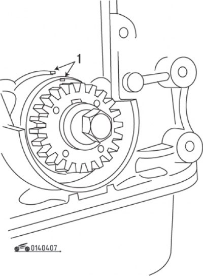
Figure 4.7. Aligning the mark (1) on the crankshaft pulley with the mark on the front cylinder block cover
Make sure that the mark on the crankshaft pulley matches the mark on the front cylinder block cover (figure 4.7), and the mark on the camshaft pulley matches the mark on the rear timing belt cover. If necessary, rotate the pulleys until all marks are aligned.
Install the timing belt onto the pulleys. Place the old belt in accordance with the previously applied arrow indicating the direction of belt rotation.
Caution: Make sure the belt grips the pulleys securely and does not sag.
Adjusting the belt tension
Loosen the tension roller mounting bolt enough to allow the roller to move toward the timing belt under spring force. Turn the crankshaft two revolutions clockwise until the camshaft mark aligns with the mark on the rear timing belt cover. Double check that all the marks match.
Tighten the tension roller mounting bolt to 45 Nm.
Turn the crankshaft two revolutions in the direction of engine rotation and check the alignment of the marks again.
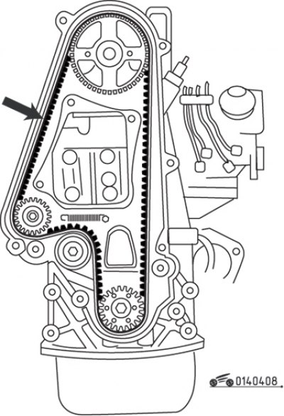
Figure 4.8. Location for checking the timing belt deflection
The toothed belt branch between the water pump and camshaft pulleys should deflect by 10.5–12.0 mm when pressing on the belt with a force of 10 kgf (strong finger pressure) (figure 4.8). Otherwise, loosen the tension roller mounting bolt and adjust the belt tension again.
Install and secure the right and left timing belt covers with bolts, tightening the bolts to a torque of 10 N·m. Install and secure the vibration damper (shock absorber) engine.
Install the crankshaft pulley with the washer and secure with bolts, tightening them to a torque of 30 Nm.
Screw in the glow plugs.
Install and tension the V-belt.
Install the cover in the right wheel arch.
Connect the cable to the negative terminal of the battery.
If you have a clock, set the time and enter the security code into the radio.
Rear toothed belt
Removal
Disconnect the cable from the negative battery terminal.
Caution! Disconnecting the negative battery cable will erase the memory of electronic memory devices, such as the radio receiver code.
Remove the glow plugs.
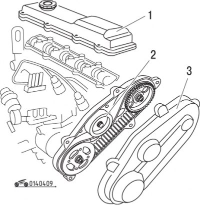
Figure 4.9. Rear toothed belt: 1 – cylinder head cover; 2 – tension roller mounting nut; 3 – toothed belt cover
Remove the bolts and the rear timing belt cover (figure 4.9).
Loosen the timing belt tension roller mounting nut.
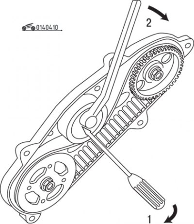
Figure 4.10. Releasing the rear timing belt tension: 1 – screwdriver; 2 – Allen key
Use a screwdriver to move the tension roller away from the timing belt and tighten the nut (figure 4.10).
Use chalk, marker or paint to mark the direction of rotation of the timing belt. If the timing belt rotates in the opposite direction during installation, it will be damaged. The engine pulleys rotate clockwise.
Caution! Do not bend or twist the timing belt. Be sure to replace belts that are dirty, damaged or worn. Check that the tension roller rotates evenly and easily.
Installation
To turn the engine crankshaft, lift the front wheel of the car, engage 5th gear and turn the wheel by hand.
Caution! Never turn the engine crankshaft by the camshaft pulley to avoid overloading the front timing belt.
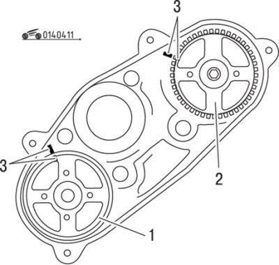
Figure 4.11. Alignment of marks (3) on the camshaft pulley (2) and high-pressure fuel pump (1) with the marks on the rear timing belt cover
Rotate the camshaft and fuel pump pulleys to positions such that the marks on the pulleys align with the marks on the rear timing belt cover (figure 4.11).
Install the timing belt onto the pulleys. Place the old belt in accordance with the previously applied arrow indicating the direction of belt rotation.
Caution: Make sure the belt grips the pulleys securely and does not sag.
Adjusting the belt tension
Loosen the tension roller mounting bolt so that the roller can move toward the timing belt under the force of the spring. Turn the crankshaft two revolutions clockwise until the camshaft mark aligns with the mark on the rear timing belt cover. Double check that all the marks match.
Tighten the tension roller mounting bolt to 25 Nm.
Turn the crankshaft two revolutions in the direction of engine rotation and check the alignment of the marks again.
The toothed belt branch between the pulleys of the high-pressure fuel pump and the camshaft should deflect by 9.5–12.0 mm when pressing on the belt with a force of 10 kgf (strong finger pressure). Otherwise, loosen the tension roller mounting bolt and adjust the belt tension again.
Install and bolt the timing belt cover, tightening the bolts to a torque of 10 Nm.
Screw in the glow plugs.
Connect the cable to the negative terminal of the battery.
If you have a clock, set the time and enter the security code into the radio.