
MazBook.ru
English Русский
Български
Беларускі
Український
Српски
Hrvatski
Română
Polski
Slovenský
Magyar
• Bookmark • Sitemap • Contacts •   
Cars Opel Cars Ford Cars Volkswagen Cars Audi Cars Kia Cars Renault Cars Peugeot


Familia Capella Mazda3 Mazda6 CX-? Others Articles
Capella 3 (1982-1992, petrol) Capella 3 and 4 (1982-1992) Capella 4 (1987-1992) Capella 5 (1991-1997) Capella 6 (1997-2005, petrol)

Diesel engine preheating system (Mazda Capella GC)

  • Home
  • Mazda Capella
  • Capella GC (1982-1992)
  • Power unit
  • Diesel engine
  • Diesel engine preheating system
0
When starting a cold engine, the autoignition temperature is not achieved by compression alone, so preheating of the fuel-air mixture is necessary.

For this purpose, a glow plug is screwed into each combustion chamber. It consists of a housing with a heating rod pressed into it. When voltage is applied, the heater coil in the rod heats up to a temperature of over 850°C within a few seconds, resulting in a preheating period rarely lasting more than 10 seconds. Once the preheating indicator lamp in the instrument cluster turns off, the engine can be started.

To speed up engine warm-up, on models produced since 1987, preheating continues after engine start-up. The heating duration is determined by the control unit depending on the coolant temperature. The control unit is located behind the center console under the air duct. Information about engine temperature is received by the control unit from the coolant temperature sensor. Based on the received data, the control unit determines the duration and strength of the current.

Checking the engine preheating system


If you have difficulty starting the engine, first measure the compression in the engine cylinders. If the compression is too low, the engine will not start at low ambient temperatures.

Checking glow plugs


Loosen the nuts and disconnect the wires from the glow plugs.
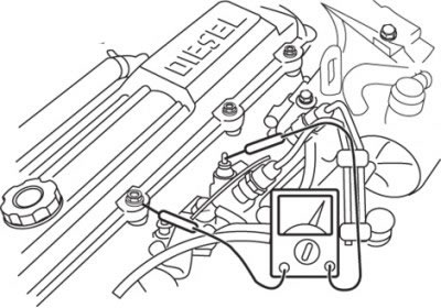
Figure 4.17. Using an ohmmeter to measure the resistance between the glow plug contact and the…

Figure 4.17. Using an ohmmeter to measure the resistance between the glow plug contact and the cylinder block


Connect an ohmmeter in series to each glow plug and check the resistance between the glow plug contact and the cylinder block (figure 4.17).

If the resistance is not zero, the glow plug is faulty and must be replaced.
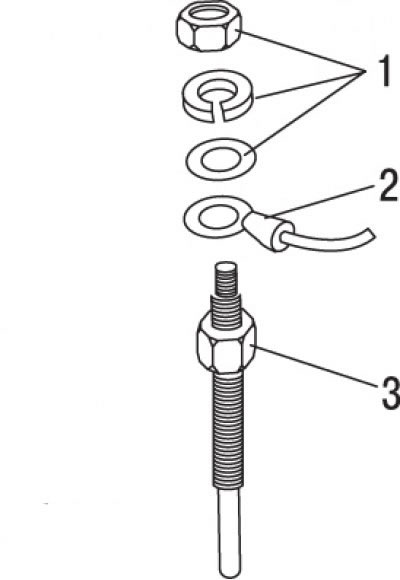
Figure 4.18. Glow plug: 1 – nut with washers; 2 – connecting wire; 3 – candle

Figure 4.18. Glow plug: 1 – nut with washers; 2 – connecting wire; 3 – candle


Remove the faulty glow plug. Screw in a new glow plug and tighten it to 20 Nm (figure 4.18).

Connect the wire to the glow plug and secure it with a nut and washers.

Caution! Do not exceed the specified tightening torque, as this may damage the glow rod and cause premature spark plug failure. Make sure that no oil or fuel comes into contact with the glow plug.


Glow plugs with burnt heating rods
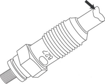


Figure 4.19. Glow plug with a burnt rod

Figure 4.19. Glow plug with a burnt rod


Burning of glow plug rods (figure 4.19) is often a consequence of faulty fuel injectors. Such damage should not be classified as internal or external defects of the glow plug.

Text taken from an online platform: MAZBOOK.ru

Caution! If damage is not detected and the engine starts poorly, inspect the glow plugs visually with the preheater on. To do this, remove the fuel injectors and observe the glow plugs through the holes during warm-up.


If such glow plugs are detected, it is not enough to simply replace them. In this case, it is also necessary to check the fuel injectors for injection pressure and tightness.

Checking the glow plug relay
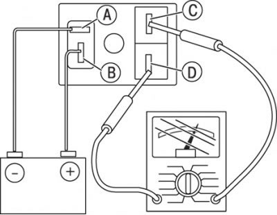


Figure 4.20. Connecting the glow plug relay to the battery terminals and checking the relay contact…

Figure 4.20. Connecting the glow plug relay to the battery terminals and checking the relay contact closure


Disconnect the glow plug relay connector. Using two additional wires, connect the relay to the battery terminals as shown in the figure 4.20, and check if the relay contacts close.

If the relay contacts do not close, replace the relay.
This article is available at: russian, bulgarian, belarusian, ukrainian, serbian, croatian, romanian, polish, slovak, hungarian
This text was checked by: Georgy Afanasyev
Share with friends on social networks:

Previous
Capella 3 and 4 » Diesel engine
Next

Removal and installation the timing belt/setting the valve timing of…
General information about diesel engines
Removal air from the fuel supply system
Checking/replacing the fuel shut-off solenoid valve
Checking and adjusting the engine crankshaft speed at idle speed
Fuel injectors — removal and installation
RF Engine Vacuum Pump — removal and installation
More articles on repairing other Mazda models
Diesel engine preheating system Mazda Familia 6 (1989-1994)
Engine Cooling System Components (Diesel) Mazda3 BK (2003-2009)
Engine Management System Fault Codes Mazda6 GG (2002-2008)
Diesel Engine Intake System Vacuum Hose Routing Diagram Mazda CX-5KE (2012-2017)
Diagram 11. Endura-CE engine preheating system Mazda 121 (3) (1996-2003)
Link in different formats to this article
Comments and feedback from visitors
No comments yet


How much will 34 + 44 ?


Capella 6 (1997-2005, petrol) 
  • General information
  • Introduction to guide
  • User manual
  • Troubleshooting
  • Maintenance
  • Power unit
  • 4-cylinder engines
  • 6-cylinder engines
  • Engine overhaul
  • Cooling and ventilation
  • Power and exhaust systems
  • Engine electrics
  • Control system
  • Transmission
  • Mechanical gearbox
  • Automatic gearbox
  • Clutch and drive shafts
  • Chassis
  • Brake system
  • Car suspension
  • Steering
  • Body
  • Exterior (external elements)
  • Interior (internal elements)
  • Doors, windows and locks
  • Electrical equipment
  • Equipment and devices
  • Electrical circuits
Capella 5 (1991-1997) 
  • General information
  • User manual
  • Maintenance
  • Helpful hints
  • Power unit
  • Petrol engines 1.6 and 1.8
  • Petrol engines 2.0
  • 2.5 petrol engines
  • Overhaul engines 1.6 and 1.8
  • Overhaul engines 2.0 and 2.5
  • Diesel engine 2.0
  • Engine electrics
  • Cooling system
  • Air conditioner
  • Carburetor Nikki 30/34
  • Power system (1.6 and 1.8)
  • Power system (2.0 and 2.5)
  • Control system
  • Transmission
  • Mechanical gearbox
  • Automatic gearbox
  • Clutch and axles
  • Chassis
  • Brake system
  • Suspension and wheels
  • Steering
  • Body
  • Exterior (external elements)
  • Interior (internal elements)
  • Doors and windows
  • Electrical equipment
  • Equipment and devices
  • Electrical circuits
Capella 4 (1987-1992) 
  • General information
  • Introduction to manual
  • Vehicle specifications
  • Power unit
  • Engine repair
  • Lubrication system
  • Cooling system
  • Fuel system (carburetor)
  • Fuel injection (FE)
  • Fuel injection (DOHC)
  • Fuel system (diesel)
  • Ignition system
  • Transmission
  • Clutch
  • Gearbox
  • Drive shafts
  • Chassis
  • Front suspension
  • Rear suspension
  • Steering system
  • Brake system
  • Electrical equipment
  • Equipment and devices
  • Electrical circuits
Capella 3 and 4 (1982-1992) 
  • General information
  • User manual
  • Maintenance
  • Power unit
  • Gasoline engine
  • Engine overhaul (gasoline)
  • Diesel engine
  • Cooling and heating
  • Supply system
  • Ignition system
  • Emission reduction
  • Transmission
  • Clutch
  • Mechanical gearbox
  • Automatic gearbox
  • Drive shafts
  • Chassis
  • Brake system
  • Suspension and wheels
  • Steering
  • Body
  • Exterior (external elements)
  • Interior (internal elements)
  • Electrical equipment
  • Equipment and devices
  • Power devices
  • Electrical circuits
Capella 3 (1982-1992, petrol) 
  • General information
  • User manual
  • Maintenance
  • Troubleshooting
  • Late models
  • Power unit
  • Engine in car
  • Engine overhaul
  • Cooling and heating system
  • Fuel and exhaust system
  • Engine electrical system
  • Emission control system
  • Transmission
  • Mechanical gearbox
  • Automatic gearbox
  • Clutch and drive shafts
  • Chassis
  • Brake system
  • Suspension and wheels
  • Steering
  • Body
  • Exterior (external elements)
  • Interior (internal elements)
  • Electrical equipment
  • Equipment and devices
  • Lighting and lamps
  • Electrical circuits
MazBook.ru © 2018–2026 · Mobile version · Articles and news · Sitemap: EN BG BY UA RS HR RO PL SK HU · Feedback · Site search · Add to bookmarks Familia 5 (BF) · Familia 6 (BG) · Capella 3 (GC) · Capella 3 and 4 (GC) · Capella 4 (GD) · Capella 5 (GE) · Capella 6 (GF) · Mazda3 BK · Mazda6 GG · CX-5KE · Mazda 121 (3) · Mazda BT-50 (1) ·
By continuing to use the site, you agree to the use of cookies 🔐