
Technical specifications
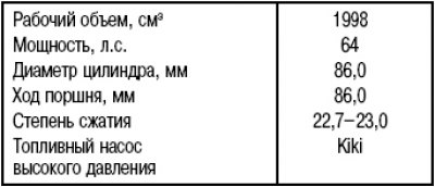
Working principle of diesel engine
In a diesel engine, air is drawn into the cylinders where it is subjected to a very high compression ratio. Due to this, the temperature in the cylinders becomes higher than the ignition temperature of diesel fuel - diesel fuel ignites, so spark plugs are not required here. On a cold engine, the ignition temperature of the fuel cannot be reached only due to a high compression ratio. In this case, the engine warms up (engine preheating). For this, a glow plug is used in each swirl chamber of a diesel engine, which heats up the combustion chamber. Fuel is sucked directly by the high pressure fuel pump (injection pump) from the fuel tank. The pump generates the necessary high pressure (about 130 bar), and the fuel is distributed to the cylinders in accordance with the ignition sequence. At the same time, the injection pump regulator doses the fuel supply depending on the degree of depression on the accelerator pedal. At a certain point in time, diesel fuel is injected through nozzles into the prechamber of the corresponding cylinder. Depending on the shape of the prechamber or swirl chamber, the intake air is forced into a swirling motion by compression, which contributes to an optimal mixing of air and injected fuel.
Before entering the high pressure fuel pump, the fuel passes through the fuel filter and is cleaned of contaminants and water. Therefore, it is especially important to drain the water from the filter or replace it in accordance with the maintenance schedule.
The high pressure fuel pump is maintenance free. All moving parts of the pump are lubricated with diesel fuel. The pump is driven by a toothed belt.
Since the diesel engine self-ignites the fuel, it cannot be stopped by turning off the ignition, so the engine is equipped with a solenoid valve. When the ignition is turned off, the valve is powered off and it closes the fuel supply channel. This ensures that the fuel supply is cut off before the steering wheel locks when the key is removed from the switch (castle) ignition. When the engine is started, voltage is applied through the ignition switch to the solenoid valve and it opens the fuel supply channel.
Attention! Keep cleanliness when working on the diesel injection device.
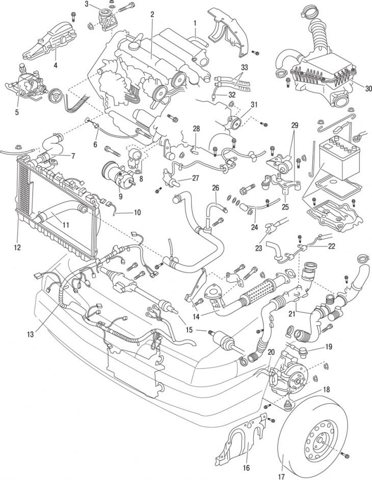
Pic. 4.1. Location of the main elements of the diesel engine and vehicle elements in the engine compartment: 1 - heater hoses; 2 – diesel engine; 3 – an arm of a support of the engine; 4 - casing of V-belts; 5 - power steering pump; 6 - accelerator cable; 7 - radiator hose; 8 - engine support bracket; 9 - air conditioner compressor; 10 - radiator fan wire; 11 - radiator hose; 12 - fan and radiator; 13 - engine wiring harness; 14 - elements of the exhaust gas system; 15 - drive shaft; 16 - side casing of the engine; 17 - wheel; 18 - lower transverse lever; 19 – a tip of steering draft; 20 - stabilizer bar; 21 - air pipes; 22 – a hose of brake system; 23 - gearshift rod; 24 – draft of a choice of transfers; 25 - battery with stand; 26 - heater hoses; 27 - clutch slave cylinder; 28 – a plait of wires of a transmission; 29 - engine mounts; 30 - air filter; 31 - engine support bracket; 32 - speed sensor; 33 - fuel lines
The location of the main elements of the diesel engine and elements in the engine compartment is shown in fig. 4.1.