


Contents: When starting the engine ⇓ Advance opening or closing of valves ⇓ Delay in opening or closing of valves ⇓ Intermediate opening or closing of…⇓
The variable valve timing actuator has two hydraulic chambers: a valve advance chamber and a valve retard chamber. The chambers are located between the integrated camshaft sprocket housing and the camshaft rotor. An oil pump supplies engine oil to each chamber. The hydraulic pressure in each chamber is controlled by an oil control valve (OCV), and the relative phases of the camshaft sprocket and camshaft are varied to obtain the optimum valve opening or closing timing according to engine operating conditions.
When starting the engine
When the pin in the variable valve timing actuator rests against the rotor, which is in the position of maximum valve opening or closing retardation under the action of the spring, the camshaft sprocket and camshaft rotate as a single part. When the oil pressure increases and the pin moves away from the rotor, it becomes possible to modify the relative angular position of the camshaft sprocket and camshaft.
Advance opening or closing of valves
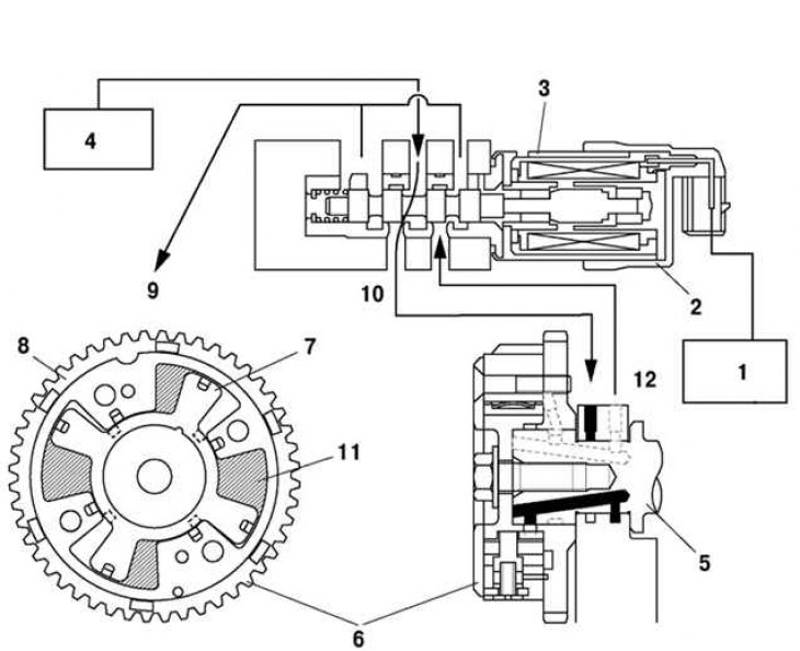
Fig. 2.33. Oil circulation diagram during valve opening or closing advance: 1 – PCM block; 2 – Oil control valve (OCV); 3 – spool valve; 4 – oil pump; 5 – camshaft; 6 – actuator for changing valve timing; 7 – rotor; 8 – body; 9 – oil pan; 10 – to the valve opening or closing advance section; 11 – valve opening or closing advance section; 12 – from the valve opening or closing delay section
When the spool valve in the oil control valve (OCV) moves to the left according to the signal from the PCM, the pressurized oil flows into the valve advance passage and into the valve advance section of the variable valve timing actuator. Then the rotor combined with the camshaft rotates in the valve advance direction against the housing driven by the crankshaft, and the valve opening or closing timing shifts toward the advance direction (Fig. 2.33).
The text of the article is taken from the website MAZBOOK.RU
Delay in opening or closing of valves
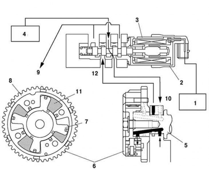
Fig. 2.34. Oil circulation diagram during delayed opening or closing of valves: 1 – PCM block; 2 – Oil control valve (OCV); 3 – spool valve; 4 – oil pump; 5 – camshaft; 6 – actuator for changing valve timing; 7 – rotor; 8 – body; 9 – oil pan; 10 – to the valve opening or closing delay section; 11 – valve opening or closing delay section; 12 – from the valve opening or closing advance section
When the spool valve in the oil control valve (OCV) moves to the right according to the signal from the PCM, oil from the oil pump is supplied under pressure to the valve opening or closing retard passage and the valve opening or closing retard section of the variable valve timing actuator. Then the rotor combined with the camshaft rotates in the valve opening or closing retard direction against the housing, which is driven by the crankshaft, and the valve opening or closing timing shifts toward the retard direction (Fig. 2.34).
Intermediate opening or closing of valves
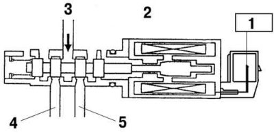
Fig. 2.35. Oil circulation diagram during intermediate opening or closing of valves: 1 – PCM block; 2 – Oil control valve (OCV); 3 – spool valve; 4 – to the valve opening or closing advance section; 5 – to the valve opening or closing delay section
The spool valve in the oil control valve (OCV) is located in an intermediate position. Hydraulic pressure is maintained in both the advance and retard sections of the variable valve timing actuator. At the same time, the relative rotation angle of the rotor and housing does not change, which provides a fixed moment of opening or closing of the valves (Fig. 2.35).