


Repair of diesel engines Mazda 3 (BK)

Diesel Engine Components
Fig. 2.232. Z6 engine components: 1 – drive belt; 2 – automatic drive belt tensioner; 3 – valve tappet; 4 - timing mechanism drive chain; 5 – cylinder head gasket; 6 –...
Fig. 2.232. Z6 engine components: 1 – drive belt; 2 – automatic drive belt tensioner; 3 – valve tappet; 4 - timing mechanism drive chain; 5 – cylinder head gasket; 6 –...

Checking the accessory drive belt
Fig. 2.233. Checking the drive belt tension Check the position of the drive belt automatic tensioner indicator mark (fig. 2.233). If the position of the mark is not...
Fig. 2.233. Checking the drive belt tension Check the position of the drive belt automatic tensioner indicator mark (fig. 2.233). If the position of the mark is not...

Replacing the drive belt
Remove the bottom cover and splash guard (right). Fig. 2.234. Loosening the drive belt tension Turn the automatic drive belt tensioner in the direction shown in Figure...
Remove the bottom cover and splash guard (right). Fig. 2.234. Loosening the drive belt tension Turn the automatic drive belt tensioner in the direction shown in Figure...

Checking the automatic drive belt tensioner
Remove the drive belt. Fig. 2.235. Checking the automatic drive belt tensioner: 1 – Automatic drive belt tensioner Check the smooth movement of the automatic drive belt...
Remove the drive belt. Fig. 2.235. Checking the automatic drive belt tensioner: 1 – Automatic drive belt tensioner Check the smooth movement of the automatic drive belt...

Checking thermal clearances in the valve drive mechanism
Remove the battery cover. Disconnect the negative cable from the battery. Remove the bottom cover and splash guard (right). Remove the air filter assembly. Remove the...
Remove the battery cover. Disconnect the negative cable from the battery. Remove the bottom cover and splash guard (right). Remove the air filter assembly. Remove the...

Adjusting thermal clearances in the valve drive mechanism
Remove the battery cover. Disconnect the negative cable from the battery. Remove the front wheel and tire (right). Remove the air filter assembly. Remove the ignition...
Remove the battery cover. Disconnect the negative cable from the battery. Remove the front wheel and tire (right). Remove the air filter assembly. Remove the ignition...

Checking the compression in the cylinders
Warning: A hot engine can cause serious burns. Caution: Be careful not to get burned when removing and installing engine components. Make sure the battery is fully...
Warning: A hot engine can cause serious burns. Caution: Be careful not to get burned when removing and installing engine components. Make sure the battery is fully...

Components of the timing chain
Remove the battery cover. Disconnect the negative cable from the battery. Drain the coolant from the engine. Remove the following items: front wheel (right); bottom...
Remove the battery cover. Disconnect the negative cable from the battery. Drain the coolant from the engine. Remove the following items: front wheel (right); bottom...

Removal the timing chain tensioner
Press the chain tensioner connector plate through the access hole on the left side using a thin flat-head screwdriver (precision screwdriver). Fig. 2.256. Chain...
Press the chain tensioner connector plate through the access hole on the left side using a thin flat-head screwdriver (precision screwdriver). Fig. 2.256. Chain...

Removal the timing chain
Fig. 2.258. Alignment of the crankshaft sprocket keyway with the timing mark Rotate the crankshaft clockwise and align the keyway of the crankshaft sprocket with the...
Fig. 2.258. Alignment of the crankshaft sprocket keyway with the timing mark Rotate the crankshaft clockwise and align the keyway of the crankshaft sprocket with the...

Installing the timing chain
Fig. 2.260. Alignment of the crankshaft sprocket keyway with the installation mark Align the crankshaft sprocket keyway with the timing mark, then set the piston of the...
Fig. 2.260. Alignment of the crankshaft sprocket keyway with the installation mark Align the crankshaft sprocket keyway with the timing mark, then set the piston of the...

Installing Engine Support #3
Fig. 2.266. Tightening the studs for fastening engine support No.3 Tighten the engine mount studs #3 (fig. 2.266). Tightening torque: 7–13 Nm. Install engine support #3...
Fig. 2.266. Tightening the studs for fastening engine support No.3 Tighten the engine mount studs #3 (fig. 2.266). Tightening torque: 7–13 Nm. Install engine support #3...

Installing the crankshaft pulley mounting bolt support
Secure the crankshaft pulley using special tools. Tighten the crankshaft pulley mounting bolt. Tightening torque: 157–167 Nm.
Secure the crankshaft pulley using special tools. Tighten the crankshaft pulley mounting bolt. Tightening torque: 157–167 Nm.

Installing the cylinder head cover
Fig. 2.268. Scheme for applying silicone sealant Apply silicone sealant as shown in Figure 2.268. Thickness of the applied sealant bead: 2–6 mm. Length of the applied...
Fig. 2.268. Scheme for applying silicone sealant Apply silicone sealant as shown in Figure 2.268. Thickness of the applied sealant bead: 2–6 mm. Length of the applied...
Final installation of the timing chain
Install the remaining components in the reverse order of removal. Start the engine. Check and adjust the following if necessary: engine oil level; pulley and belt;...
Install the remaining components in the reverse order of removal. Start the engine. Check and adjust the following if necessary: engine oil level; pulley and belt;...
Replacing the cylinder block gasket
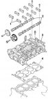
Fig. 2.270. Cylinder block gasket: 1 – camshaft bearing cap; 2 – camshaft; 3 – cylinder head; 4 – cylinder head gasket Removal Remove the timing chain. Remove the EGR...
Fig. 2.270. Cylinder block gasket: 1 – camshaft bearing cap; 2 – camshaft; 3 – cylinder head; 4 – cylinder head gasket Removal Remove the timing chain. Remove the EGR...

Installing the camshaft bearing cap
Set the camshaft to TDC position of cylinder No.1, and install the camshaft. Fig. 2.275. Installation positions of camshaft bearing caps Install the camshaft bearing...
Set the camshaft to TDC position of cylinder No.1, and install the camshaft. Fig. 2.275. Installation positions of camshaft bearing caps Install the camshaft bearing...

Replacing the front crankshaft oil seal
Fig. 2.277. Crankshaft pulley: 1 – crankshaft pulley mounting bolt; 2 – crankshaft pulley; 3 – front oil seal Removal Remove the battery cover. Disconnect the negative...
Fig. 2.277. Crankshaft pulley: 1 – crankshaft pulley mounting bolt; 2 – crankshaft pulley; 3 – front oil seal Removal Remove the battery cover. Disconnect the negative...

Replacing the rear crankshaft oil seal
Removal Remove from automatic transmission model: gearbox; leading disk. Remove from manual transmission model: clutch slave cylinder; manual transmission in block with...
Removal Remove from automatic transmission model: gearbox; leading disk. Remove from manual transmission model: clutch slave cylinder; manual transmission in block with...
Removal and installation the engine
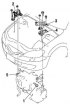
Fig. 2.281. Powertrain components: 1 – Main fuse box connector; 2 – Engine support No.3; 3 – battery platform bracket; 4 – Engine support No.4; 5 – engine, gearbox in...
Fig. 2.281. Powertrain components: 1 – Main fuse box connector; 2 – Engine support No.3; 3 – battery platform bracket; 4 – Engine support No.4; 5 – engine, gearbox in...
This section is available on: russian, bulgarian, belarusian, ukrainian, serbian, croatian, romanian, polish, slovak, hungarian
More sections on repairs of other Mazda models
• Power unit: Diesel engines Mazda Familia 6 (1989-1994)
• Power unit: Diesel engine Mazda Capella 3 and 4 (1982-1992)
• Power unit: Diesel engines 2.2 l Mazda CX-5KE (2012-2017)
• Power unit: Diesel engine Mazda 121 (3) (1996-2003)
• Power unit: Diesel engines Mazda Familia 6 (1989-1994)
• Power unit: Diesel engine Mazda Capella 3 and 4 (1982-1992)
• Power unit: Diesel engines 2.2 l Mazda CX-5KE (2012-2017)
• Power unit: Diesel engine Mazda 121 (3) (1996-2003)
Link in different formats to this section
TEXTHTMLBB Code
- User manual
- Vehicle description
- Keys, locks and alarms
- Controls and instruments
- Air conditioning and heater
- Seat adjustment
- Security systems
- Driving and operation
- Faults en route
- Maintenance
- Power unit
- Engine device (gasoline)
- Engine repair (gasoline)
- Diesel engine (Z6)
- Lubrication system
- Cooling system
- Fuel system
- Exhaust system
- Engine electrical equipment
- Engine management system
- Transmission
- Clutch
- Mechanical gearbox
- Automatic gearbox
- Drive mechanism
- Chassis
- Suspension and wheels
- Steering
- Brake system
- Body
- Body elements
- Doors and windows
- Air conditioning and heater
- Electrical equipment
- Equipment and devices
- Power devices
- Lighting system
- Windshield wipers and washers
- Equipment checks