


Contents: Removal ⇓ Removal the main fuse box connector ⇓ Removal engine mounts #3 and #4 ⇓ Removal the engine mount and No.4 ⇓ Installing the engine mount and No.4 ⇓ Installing Engine Support #3 ⇓
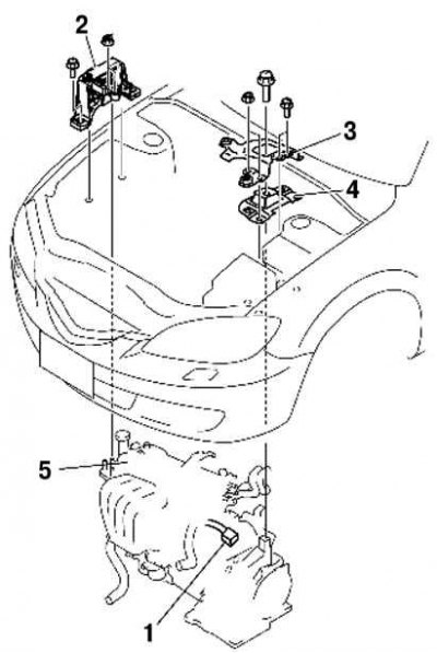
Fig. 2.281. Powertrain components: 1 – Main fuse box connector; 2 – Engine support No.3; 3 – battery platform bracket; 4 – Engine support No.4; 5 – engine, gearbox in block with final drive
Removal
Note: Removal and installation of the engine and gearbox in block with the main gear is performed from underneath the vehicle.
Remove the following items:
- battery cover, battery box, battery mounting bracket, battery pack and battery pad;
- front wheels;
- bottom cover and mudguards;
- air duct, air hose and air filter assembly;
- accelerator cable and bracket;
- drive belt.
- Drain the following liquids:
- automatic transmission fluid or transmission oil in the block with the main gear;
- engine coolant;
- working fluid of the power steering system.
Disconnect the purge valve hose.
Disconnect the power steering return hose from the power steering oil pump.
Disconnect the power steering pressure line from the steering gear.
Disconnect the power steering return hose from the power steering reservoir.
Remove the following items:
- front crossmember, front stabilizer, lower arm, steering gear and engine mount element #1;
- drive shaft;
- power steering reservoir with hose;
- expansion tank of the cooling system with a hose;
- cooling system fan unit;
- automatic transmission fluid hose, gear selector cable and wiring harness (models with automatic transmission);
- gear selector cable and shift drive cable (models with manual transmission);
- clutch slave cylinder with tube (models with manual transmission);
- ground (engine support no. 3);
- air conditioning compressor with tubes.
Note: Secure the air conditioning compressor with wire or rope so that it does not interfere with operation.
Disconnect the following elements:
- brake booster hose;
- fuel supply hose;
- heater radiator hose;
- upper and lower radiator hose;
- main muffler.
Caution! Do not tighten the engine support #1 mounting bolt until engine support #3 is installed.
Check and adjust the following if necessary:
- front wheel alignment angles.
- pulley and belt.
- leakage of engine oil, engine coolant, automatic transmission fluid, manual transmission fluid and fuel.
- setting the ignition timing and idle speed. Check the CO, CH value.
- operation of auxiliary equipment driven by the engine.
Note: If the vehicle is being fitted with a rebuilt engine, test drive the vehicle to ensure that everything is running properly.
Removal the main fuse box connector
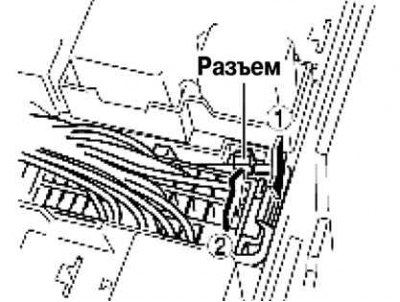
Fig. 2.282. Releasing the main fuse box connector fastening
Release the tongue as shown in Figure 2.282.
Lift the locking lever and remove the connector.
Removal engine mounts #3 and #4
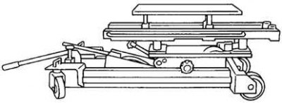
Fig. 2.283. Securing the engine on a motor jack
Secure the engine and transmission to the final drive block using an engine jack and an additional device (fig. 2.283).
Removal the engine mount and No.4
Secure the engine and gearbox to the final drive block using an engine jack and an additional device.
Installing the engine mount and No.4
Install engine mounts #1 and #4.
Note: Do not tighten the bolt and nut of engine mounts No.1 and No.4 when performing this operation.
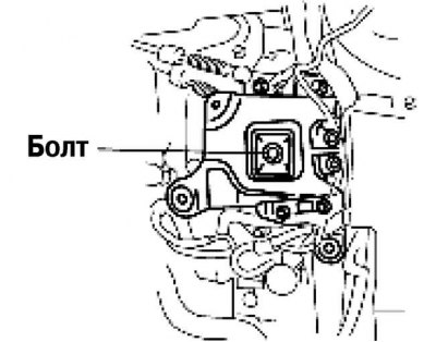
Fig. 2.284. Engine support mounting bolt No.4
Tighten engine support mounting bolt No.4, shown in Figure 2.284.
Tightening torque: 66.6–93.1 N·m.
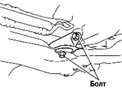
Fig. 2.285. Tightening the bolt securing engine support No.4 and the battery bracket
Tighten the bolt and nut securing engine support No.4 and the battery platform bracket in the order shown in Figure 2.285.
Tightening torque:
- 1 - 44–61 Nm;
- 2 - 6.9–9.8 Nm.
Installing Engine Support #3
Tighten the engine support mounting studs #3.
Tightening torque: 7–13 Nm.
Install engine support #3 and temporarily tighten the mounting bolts and nuts.
Tighten engine mount bolts #3.
Remove the engine jack and additional fixture.
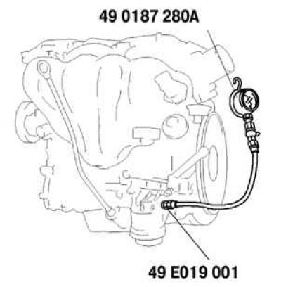
Fig. 2.286. Installing a special device for measuring oil pressure
Tighten the engine support mounting bolts #1 (fig. 2.286).
Tightening torque: 93.1–116.6 N·m.