
Disconnect the negative cable from the battery.
Remove the bottom cover and mudguard (right).
Remove the air filter assembly.
Remove ignition coils.
Disconnect the ventilation hose.
Remove the cylinder head cover.
Measure the valve clearance.
Rotate the crankshaft clockwise so that #1 piston is at TDC on the compression stroke.
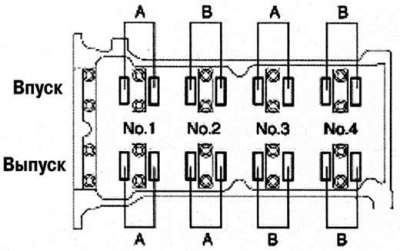
Pic. 2.236. Procedure for measuring valve clearances
Measure the valve clearance at point A (pic. 2.236).
If the clearance is not correct, replace the valve lifter and adjust the valve clearance to the average value.
Standard valve clearance (on a cold engine): 0.27–0.33 mm.
Note. Record the measured values to select the appropriate valve lifters for replacement.
Rotate the crankshaft 360°clockwise so that the #4 piston is at TDC on the compression stroke.
Measure valve clearance at point B (see fig. 2.236).
If out of specification, replace the valve lifter and adjust the valve clearance to the average value.
Standard valve clearance (on a cold engine): 0.27–0.33 mm.
Install the cylinder head cover.
Connect the ventilation hose.
Install the ignition coils.
Install the air filter assembly.
Install the bottom cover and mudguard (right).