
Removing
Disconnect the wire from the negative battery terminal.
Remove the cylinder head cover.
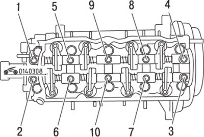
Pic. 3.8. The sequence of unscrewing the bolts of the valve drive mechanism
Loosen the bolts securing the shaft with rocker arms in the sequence shown in fig. 3.8. Unscrew the bolts gradually, turning at a small angle.
After loosening the bolts, unscrew the bolts and put them in a box with numbered cells in order to subsequently install each bolt in its original place.
Remove the camshaft cover assembly with shafts and rocker arms.
If it becomes necessary to dismantle the rocker shafts, mark the parts so that they can then be reinstalled in their original position. Rocker arms and rocker shafts are not interchangeable.
Installation
Thoroughly clean the mating surfaces of the camshaft cover and cylinder head of any residual sealant.
If the mechanism was disassembled, then before installation, generously lubricate the shaft assembly with the cover and rocker arms with clean engine oil.
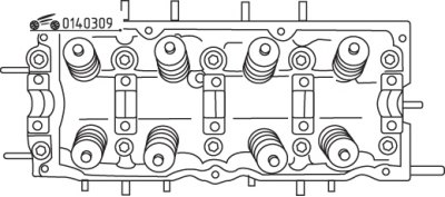
Pic. 3.9. Places (hatched) applying sealant before installing the valve actuator
Apply a layer of sealant to the mating surfaces of the camshaft cover and cylinder head as shown in fig. 3.9.
Install the valve drive mechanism, tighten the mounting bolts by hand, installing each bolt in its original place.
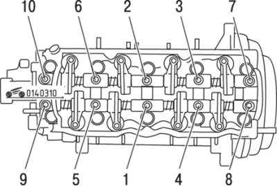
Pic. 3.10. The sequence of tightening the bolts of the valve drive mechanism
Tighten the bolts to the required torque in the sequence shown in fig. 3.10. Tighten the bolts gradually.
Check clearances between valves and rocker arms, adjust if necessary.
Install the cylinder head cover and connect the wire to the negative battery terminal.