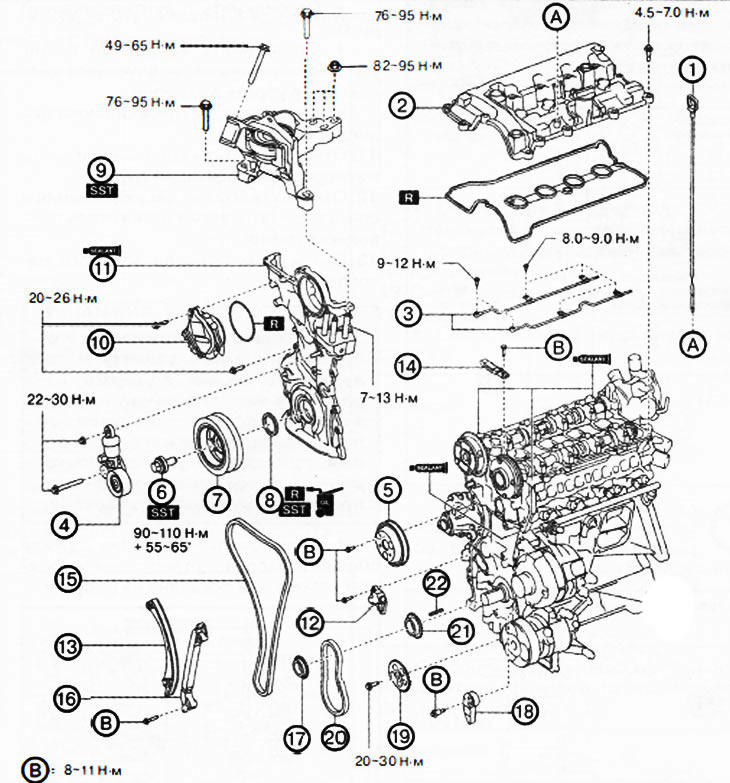
1. Oil dipstick.
2. Cylinder head cover.
3. Oil spray tubes.
4. Automatic drive belt tensioner.
5. Water pump pulley.
6. Crankshaft pulley bolt.
7. Crankshaft pulley.
8. Front crankshaft oil seal.
9. Engine support No. 3.
10. Electric drive for changing the valve timing.
11. Engine front cover.
12. Drive chain tensioner.
13. Tensioner shoe.
14. Chain guide (№1).
15. Timing chain drive.
16. Chain guide (№2).
17. Crankshaft sprocket.
18. Oil pump chain tensioner.
19. Oil pump drive sprocket.
20. Oil pump drive chain.
21. Oil pump drive sprocket.
22. Key.
Attention.
- A hot engine can cause burns. Before starting work, turn off the engine and wait until it cools down.
- If the camshaft rotates after the drive chain is removed, the valves may hit the piston crown when the piston is at top dead center, causing engine damage. When rotating the camshaft with the drive chain removed, it is necessary to set all the engine pistons to the middle position.
- When turning the camshaft with a wrench on the hex part, the wrench may rest against the rocker and damage it. To prevent damage to the rocker arm, when holding the camshaft by the hex part, place the wrench closer to the rear of the engine, as shown in the figure, to ensure a safe gap between the wrench and the camshaft cam.
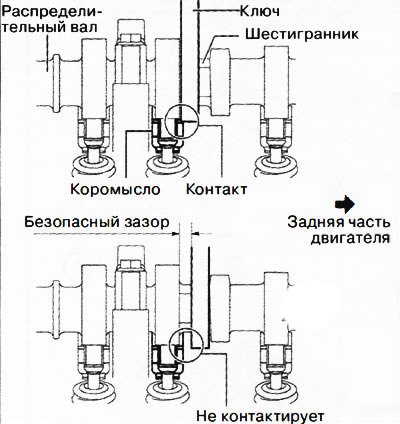
Note: The width of the hex part of the camshaft is 22-24mm.

1. Disconnect the negative battery terminal.
2. Remove the decorative engine cover.
3. Remove ignition coils/ion sensors.
4. Remove the front protective tray #2.
5. Remove mudguard.
6. Remove attachment drive belts.
7. Drain engine oil.
8. Remove the oil pan.
9. Remove the oil dipstick from the engine.
10. Remove the cylinder head cover:
- Disconnect the oil control valve connector.
- Remove the clips securing the wiring harness to the cylinder head cover.
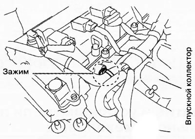
- Remove the clamp securing the wiring harness to the intake manifold as shown in the illustration and set the wires aside.
Disconnect the ventilation hose.
Disconnect the brake booster vacuum hose from the intake manifold and set aside.
Remove the cylinder head cover.
11. To turn away bolts of fastening and to remove oil-spraying tubes.
12. Unscrew the fastening bolt and nut and remove the automatic drive belt tensioner.
13. Remove the water pump drive pulley:
Attention. Be careful not to damage the groove and surface of the water pump pulley when using tools. Otherwise, it will cause wear or breakage of the drive belt, extraneous noise during operation, damage to the pulley and rust.
Align the hole in the water pump pulley with the hole in the water pump as shown.

Insert a suitable bolt (about 70 mm long) into the water pump hole as shown in the figure, thus preventing the water pump pulley from turning.
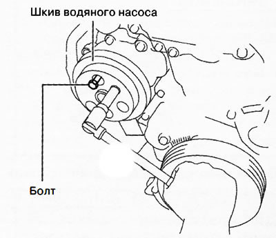
Loosen the mounting bolts and remove the water pump pulley.
Remove the bolt used to secure the water pump pulley from turning.
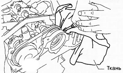
14. Remove the crankshaft pulley bolt:
Attention.
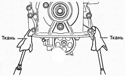
- To prevent damage to the crankshaft pulley, it is necessary to protect it with a clean cloth so that the rod part (205-072) special tool did not touch the crankshaft pulley.
- To prevent damage to the engine front cover, keep tabs out of (49 B011 105) special tool between the crankshaft pulley and the engine front cover.
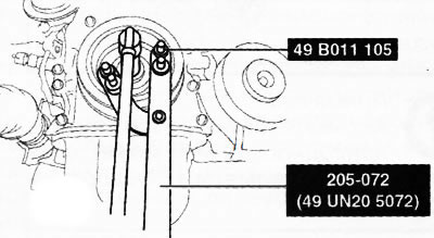
- Install special tools on the crankshaft pulley to fix it from turning.
- Loosen the crankshaft pulley bolt.
15. Remove the crankshaft pulley.
16. To take a forward epiploon of a cranked shaft.
17. Remove support No. 3 of the engine:
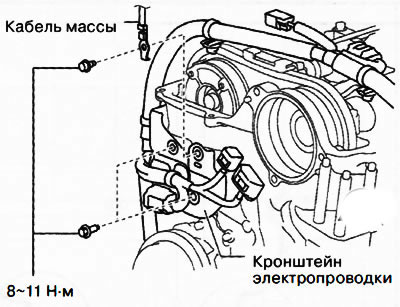
- Remove the clamps shown in the figure and move the earth cable to the side.
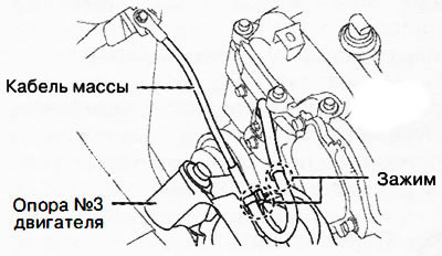
Install the special tool using part 99794 1025 or a 25 mm long M10x1.25 bolt as shown in the figure.
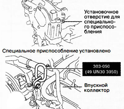
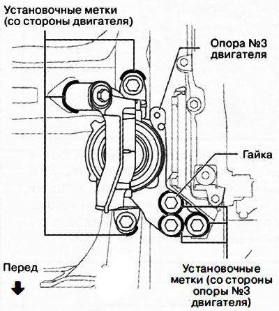
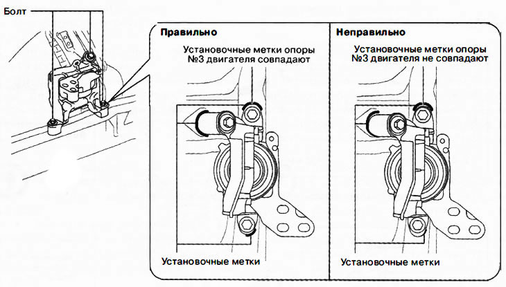
Attention. Mounting holes-supports No. 3 of the engine have an oblong shape for position adjustment. If the position of the engine support No. 3 during re-installation differs from the original position, this will lead to an increase in engine noise and vibration. Before removing engine mount #3, make alignment marks on engine mount #3 to set the mount to the same position later.

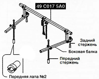
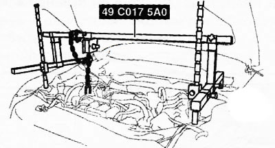
Prepare a traverse for hanging the engine 49 C017 5A0.
Attention. Follow the instructions supplied with the crosshead by the manufacturer.
Note: Install #2 front legs on the left and right traverse support rods.
Make alignment marks at the positions shown in the illustration so that you can later install the engine mount in the same position.
Note: Outline motor support #3 and fixing nuts as shown.
Protect the areas indicated in the figure with electrical tape.
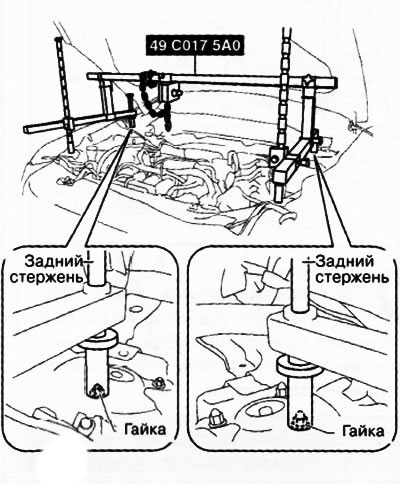
Place the rear yoke support rods on the left and right suspension strut nuts as shown in the illustration.
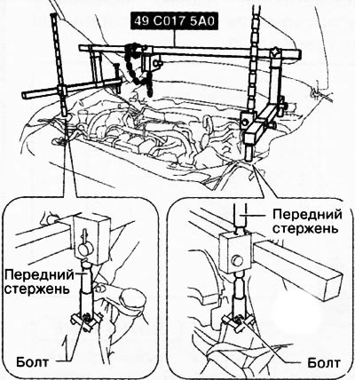
Install the front crosshead support rods on the left and right bolts.
Adjust the height of the left and right side beams of the traverse so that they are even, and then tighten all parts.
Tighten the chain connecting the yoke to the engine.
Remove engine mount #3.
18. Unscrew the mounting bolts and remove the electric drive for adjusting the valve timing.
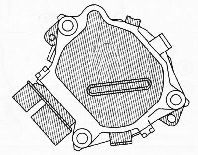
19. Remove the engine front cover:
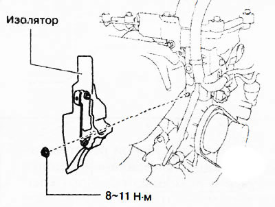
Remove the insulator shown in the figure.
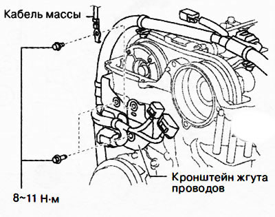
Move the earth cable and wiring harness bracket shown in the illustration to the side.
Loosen the engine front cover bolts.
Using a flat-bladed screwdriver, remove the sealant little by little and remove the engine front cover.
Attention.
- Do not apply excessive force to the screwdriver. Otherwise, you may damage the front - engine cover.
- Be careful not to scratch or damage the contact surfaces. Otherwise, oil leaks may occur later.
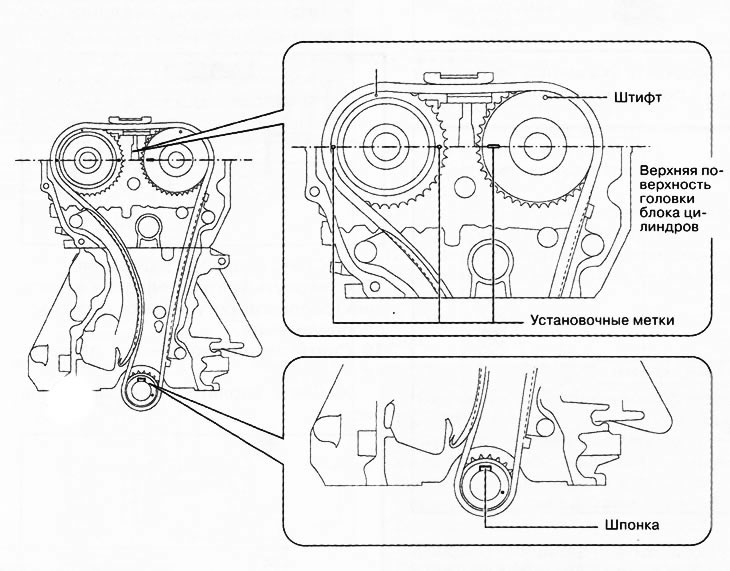
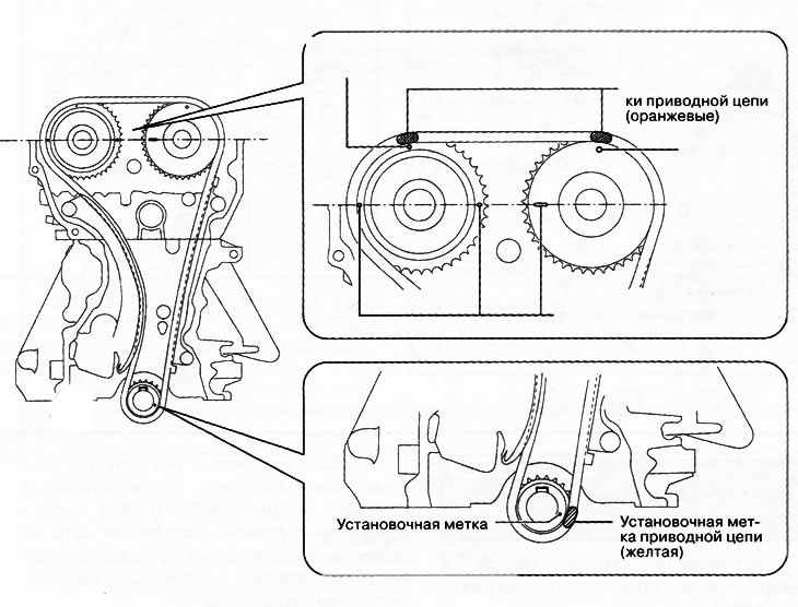
20. Rotate the crankshaft clockwise to align the timing marks and the key position as shown in the figure to set the No. 1 cylinder piston to top dead center.
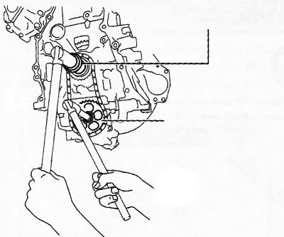
21. While moving the exhaust camshaft back and forth in the direction of the arrow in the figure, using a wrench installed on the hex part, press the drive chain tensioner plate with a screwdriver and release the plunger lock.
 | 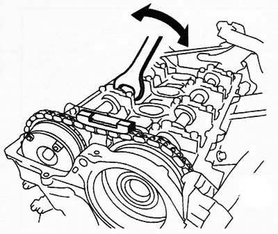 |
Note: When moving the exhaust camshaft back and forth, the drive chain will press the plunger into the tensioner, making it easier to move the plate.
22. Slowly press the plunger in the direction of the arrow in the figure with the plate pressed down.
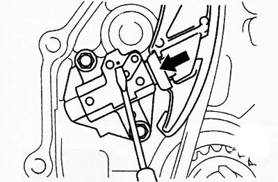
23. Remove the screwdriver from the plate while continuing to press the plunger.
24. Gradually remove the force from the plunger and move it back and forth by 2-3 mm.
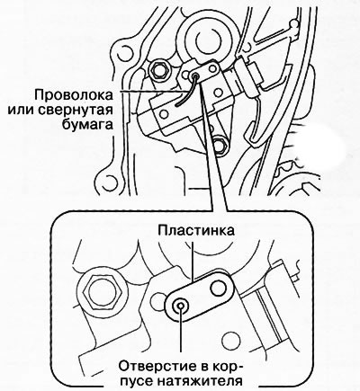
25. Insert a wire with a diameter of about 1.5 mm or rolled paper into the hole of the record and tensioner body to fix the record and block the plunger.
26. Remove the chain tensioner, tensioner shoe and chain guide #1.
27. Remove the timing chain.
28. Unscrew the fastening bolts and remove the chain damper No. 2.
29. Remove the crankshaft sprocket.
30. Unscrew the mounting bolt and remove the oil pump drive chain tensioner.
31. Remove the oil pump drive sprocket:
- Temporarily screw in the crankshaft pulley bolt and secure the oil pump from turning as shown.
- Remove the oil pump drive sprocket.
- Remove the crankshaft pulley bolt.
32. Remove the oil pump drive chain.
33. Remove the oil pump sprocket and remove the key.
34. Installation is carried out in the reverse order of removal, taking into account the following:
Install the timing chain according to the timing marks.
 |  |
Remove oil, dirt and sealant residues from the contact surfaces of the engine front cover, cylinder head and cylinder block.
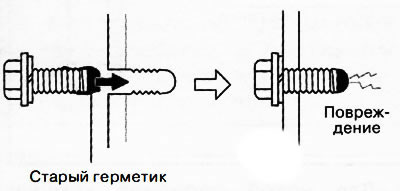
When reusing the bolts of the front cover of the engine, it is necessary to remove the remnants of the fixing composition from their threads.
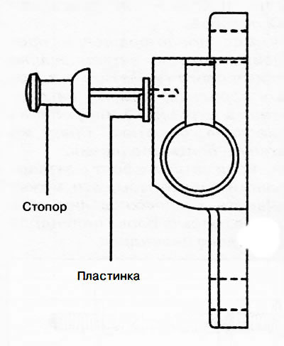
If using a new chain tensioner, remove the installed stopper.
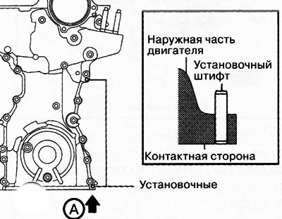
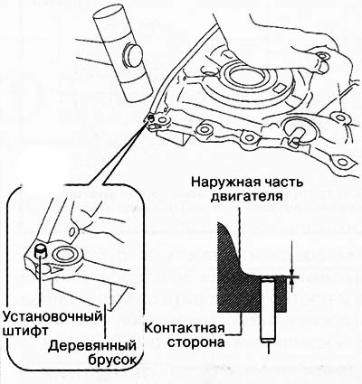
For a new engine front cover, the two dowel pins shown in the illustration protrude outside of the motor, so these dowel pins must be driven in with a hammer.
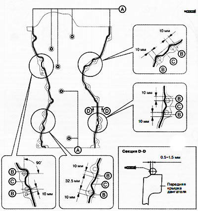
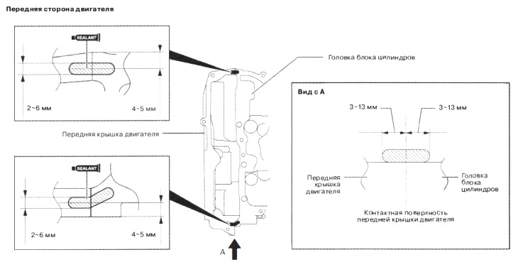
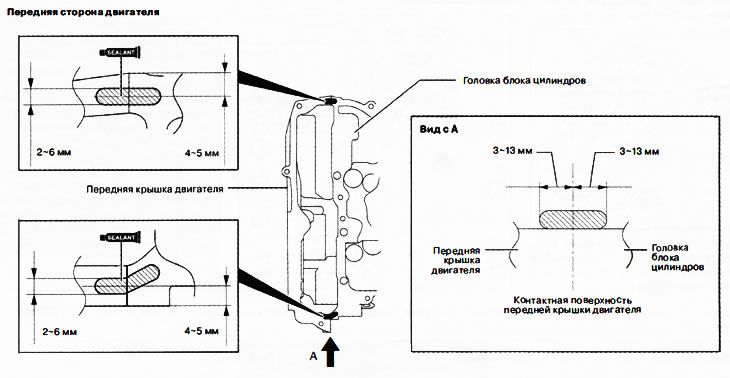
Sealant bead thickness: A: 2-6mm; B: 4-6mm; C: 4-8mm
Apply silicone sealant as shown.
Attention.
- Apply silicone sealant in an even, continuous bead.
- To prevent premature curing of the silicone sealant, install the front cover on the engine within 10 minutes of applying the sealant. Tighten the fastening bolts immediately.
- If a bolt with hardened sealant is tightened, it may cause a crack in the cylinder head or cylinder block.
Apply sealant also to the areas indicated in the following figure.
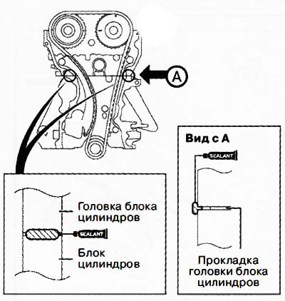
Attention. Apply silicone sealant so that it enters the cylinder head gasket.
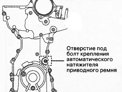
Note: Temporarily install a suitable bolt in the auto-tensioner mounting bolt hole to prevent sealant from entering the hole. Use an M8x1.25 bolt 40 mm long for this purpose.
Tighten the engine front cover mounting bolts in the sequence shown in the figure to a torque of 20-26 Nm.
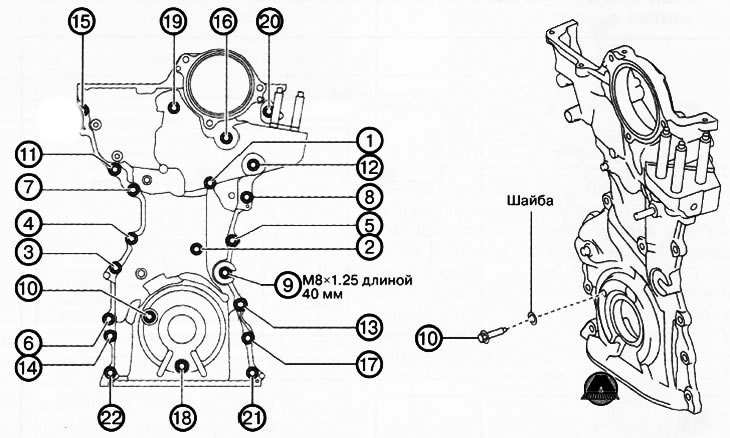
Attention. Bolt #10 must be installed with a washer.
Install ground cable and wiring bracket as shown.
Install new O-rings in the corresponding grooves on the engine front cover.
Attention. To prevent damage to the electric drive of the phase regulator, do not apply excessive force (100 N (10.2 kgf) or more) to the shaded areas in the figure.
Note:
- The eccentric shaft on the side of the electric phase regulator can rotate left and right.
- The electric drive of the phase regulator can be assembled with the connecting groove of the eccentric shaft located in any position. This does not affect the performance of the engine and does not cause any damage.
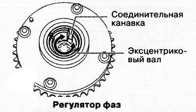
Before installation, turn the protrusion of the end of the phase regulator electric drive so that it coincides with the connecting groove on the side of the phase regulator.
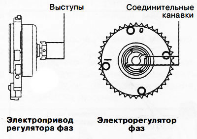
Connect the protrusions with the connecting grooves of the electric phase regulator and firmly install the electric drive on the cylinder head. Tighten the mounting bolts to 20-26 Nm.
Attention. If the position of the engine support No. 3 during re-installation differs from the original position, this will lead to an increase in engine noise and vibration. Before removing engine mount #3, make alignment marks on engine mount #3 to set the mount to the same position later.
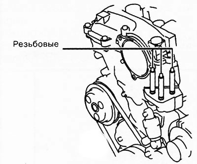
Screw the threaded studs into the engine front cover and tighten to 7-13 Nm.
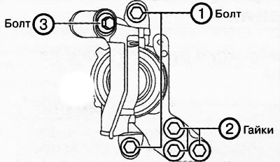
Align the alignment marks made during removal with the No. 3 engine mount and install the bolts shown in the following figure.
Install the nuts shown in the following figure, matching the matching marks on the No. 3 engine mount.
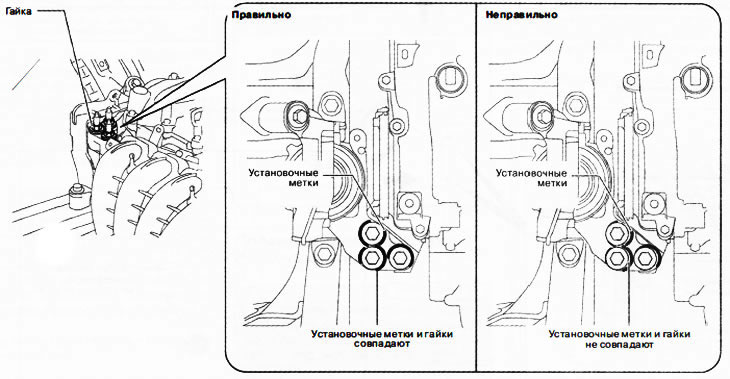
Note: If the alignment marks do not match, align them by moving the motor slightly, then screw on the nuts.
Tighten the bolts and nuts of the engine support No. 3 in the sequence shown in the figure.


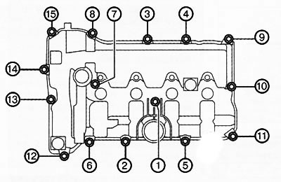
Install the oil spray pipes and tighten the mounting bolts in the sequence shown in the figure.


Attention.
- To ensure the tightness of the cylinder head cover, the following must be observed:
- Make sure the cylinder head cover gasket is inserted into the cover groove and install the cylinder head cover.
- Remove oil, dirt and sealant residues from the contact surfaces.
- To prevent premature curing of the silicone sealant, install the cylinder head cover - on the engine within 10 minutes after applying the sealant and immediately tighten the mounting bolts.
Apply silicone sealant to the areas shown in the illustration.
Tighten the cylinder head cover bolts in the sequence shown in the figure to a torque of 4.5-7.0 Nm.