
Attention.
- A hot engine can cause burns. Before starting work, turn off the engine and wait until it cools down.
- If the camshaft is rotated after the timing chain has been removed, when the piston is at top dead center, the valves may hit the piston crown, causing engine damage. When rotating the camshaft with the drive chain removed, it is necessary to set all the engine pistons to the middle position.
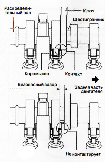
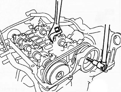
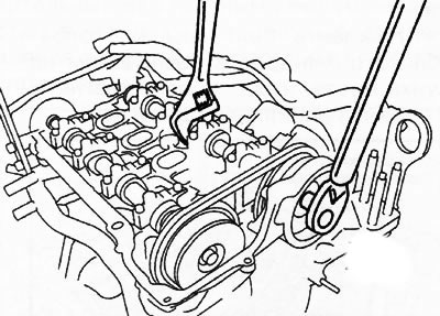
- When turning the camshaft with a wrench on the hex part, the wrench may rest against the rocker and damage it. To prevent damage to the rocker arm, when holding the camshaft by the hex part, place the wrench closer to the rear of the engine, as shown in the figure, to ensure a safe gap between the wrench and the camshaft cam.
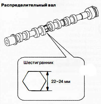
Note: The width of the hex part of the camshaft is 22-24mm.
Removing
1. Disconnect the negative battery terminal.
2. Remove the decorative engine cover.
3. Remove ignition coils/ion sensors.
4. Remove the cylinder head cover (see section "The drive chain of the gas distribution mechanism" above in this chapter).
5. Remove the front protective tray No. 2 of the engine.
6. Remove the electric drive of the valve timing regulator.
7. Remove the vacuum pump.
8. Remove the high pressure fuel pump with rear casing.
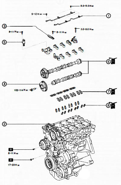
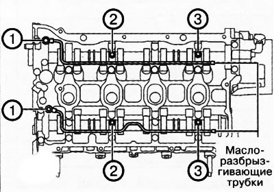
1. Oil spray pipes.
2. Timing chain drive.
3. Chain guide #1.
4. Electroregulator of gas distribution phases.
5. Oil control valve.
6. Camshafts.
7. Rocker arms.
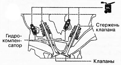
8. Hydraulic compensators.
9. To turn away bolts of fastening and to remove oil-spraying tubes.
10. Remove the timing chain with damper No. 1:
Note: Loosen the drive chain tension by locking the tensioner shoe through the service hole in the engine front cover.
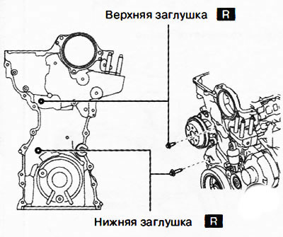
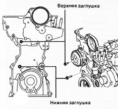
Remove plugs (top and bottom) from the service holes on the engine front cover.
Insert bolt M6 (35-60 mm long, threaded up to the head) into the upper service hole and screw it in until it contacts the tensioner shoe, then loosen it by about 180° (the bolt should rest lightly against the front of the tensioner shoe).
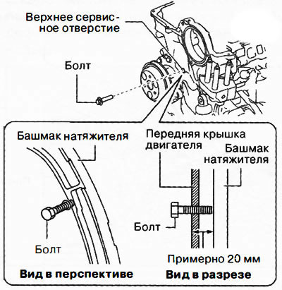
Note:
- The bolt will touch the tensioner shoe after being screwed in to a depth of approximately 20 mm.
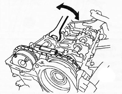
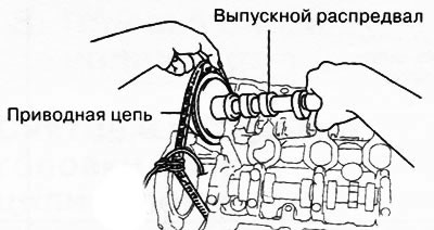
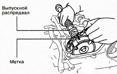
- Hold the exhaust camshaft with a wrench on the hex part, and move it back and forth several times, as shown in the figure. This will allow the oil to drain from the chain tensioner and make maintenance easier.
Insert a suitable screwdriver into the lower service hole.
While moving the exhaust camshaft back and forth with a wrench mounted on the hex part, press down the tensioner plate with a screwdriver and release the tensioner retainer.
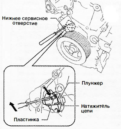
Note: When moving the exhaust camshaft back and forth, the drive chain depresses the tensioner plunger, making it easier to turn the lock plate.
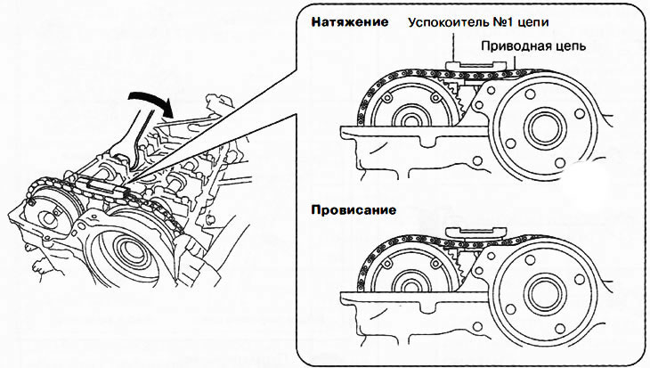
With the plunger lock released, turn the exhaust camshaft clockwise until the drive chain is loose.
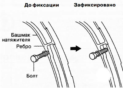
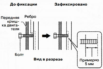
After loosening the chain, tighten the M6 bolt in the upper service hole so that it goes in about 5 mm more to secure the tensioner shoe.
 |  |
Note:
- If the bolt does not insert about 5 mm, then the tensioner plunger lock may not be released or the chain may not be loose enough. It is necessary to return the bolt to its original position and repeat the procedure again.
- When the exhaust camshaft is turned clockwise, the drive chain pushes the tensioner shoe, changing the position of its rib. The entire tensioner shoe is fixed by engaging the bolt in the rib.
After fixing the tensioner shoe, remove the chain damper No. 1.
11. Remove the electric valve timing:
Attention.
- During and after work, keep the drive chain up and away from the sprockets. If the chain falls down, it may come off the crankshaft sprocket, as a result of which it will be necessary to perform the entire procedure for setting the valve timing.
- After completing the work, it is imperative to check the installation of the gas distribution phases.
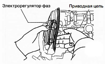
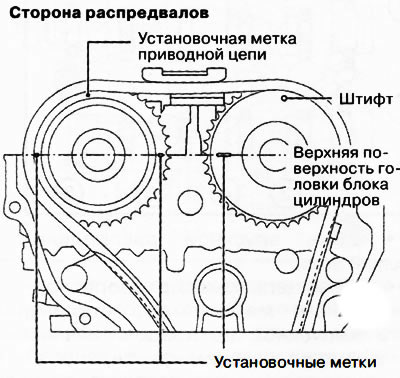
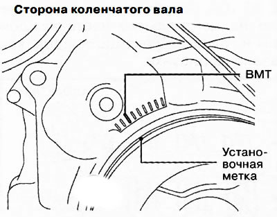
Turn the crankshaft clockwise until the piston of the first cylinder is almost at top dead center (TDC), as it shown on the picture.
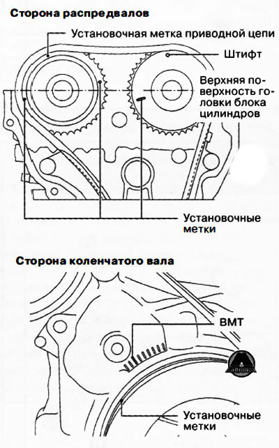
Note: When set to near top dead center (TDC) the piston of the first cylinder of the engine does not have much movement (rotation) exhaust camshaft with the drive chain removed. In this regard, the installation of an electric valve timing controller is facilitated. If there is a large movement of the exhaust camshaft, the installation of the electric valve timing on the camshaft must be carried out with a weakened circuit by rotating the exhaust camshaft.
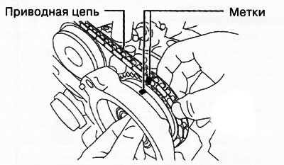
Mark the relative position of the drive chain and the phase shifters so that they are in the same position after they are reinstalled.
Holding the intake camshaft with a wrench on the hex part, unscrew the bolt securing the electrical valve timing.
Using a screwdriver wrapped in a clean cloth, push the phase adjuster slightly forward to disengage it from the camshaft.
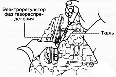
Remove the timing chain from the exhaust and intake camshaft sprockets and set aside, then remove the electric phase control.
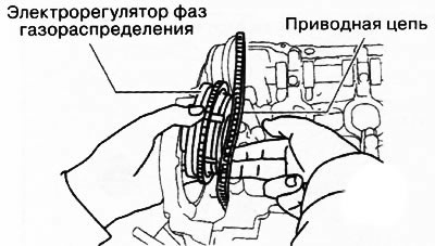
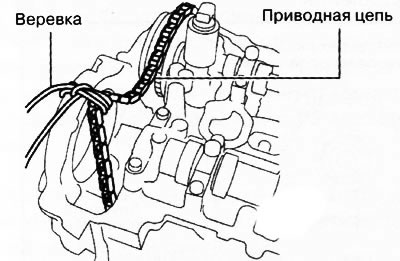
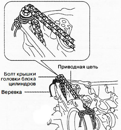
Return the drive chain to the exhaust camshaft sprocket and pull the chain up and hang it on the rope as shown in the figure.
12. Unscrew the oil control valve.
13. Remove camshafts:
Note: The exhaust camshaft and hydraulic phase shifter are removed as one assembly.
Leave the drive chain as is - suspended after removing the electric valve timing.
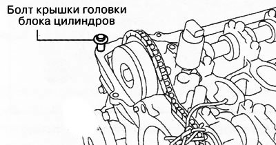
Install the cylinder head cover bolt at the location shown in the illustration to use them to hang the timing chain.
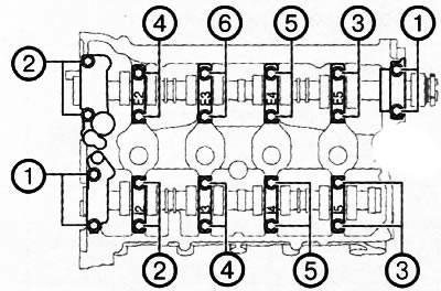
Unscrew the bolts of the camshaft covers in two or three steps in the sequence shown in the figure, then remove the covers.
Remove intake camshaft.
With the timing chain out of the way, remove the exhaust camshaft with hydraulic camshaft in one piece.
After pulling the drive chain up, hang it with a rope, as shown in the figure.
14. Remove the rocker arms from the cylinder head and arrange them in the order corresponding to the cylinders so that they can be installed in their places during assembly.
15. Remove the hydraulic lifters and arrange them in the order corresponding to the cylinders so that they can be installed in their places during assembly.
Installation
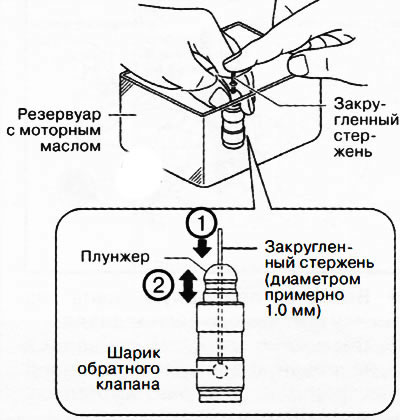
1. Remove air from hydraulic lifters:
Place the hydraulic lifter in the engine oil reservoir.
Attention. Do not insert the rounded rod with great force as the check valve ball spring is extremely weak.
Lightly pressing the check valve ball with a rounded rod (about 1.0 mm in diameter), remove the air by moving the plunger up and down.
Press the end of the plunger into the oil and make sure there is no pushing sensation. Otherwise, it is necessary to replace the hydraulic compensator with a new one.
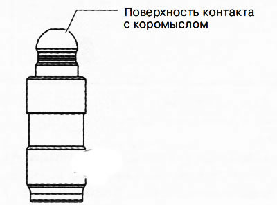
2. Visually inspect the surface of the hydraulic lifter in contact with the rocker arm for wear or damage. If any defects are found, replace the gyro compensator with a new one.
3. Install the hydraulic compensator in its original position in the cylinder head.
4. Apply engine oil to the hydraulic lifters and the ends of the valve stems, then set the rocker arms to their original positions, which they occupied before removal.
5. Install camshafts:
Apply gear oil (SAE 90 or similar) or engine oil on the center of each bearing in the cylinder head as shown.
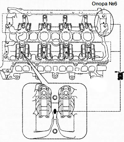
Attention. No more than 0.05 ml of oil should be applied to support No. 6.
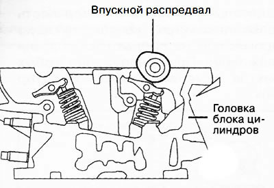
Aligning the position of the camshaft cam with the position of the almost top dead center of the piston of the first cylinder (TDC), as shown in the illustration, install the intake camshaft into the cylinder head.
Remove the rope that hangs the drive chain on the release side.
Aligning the mark on the timing chain made during removal with the mark on the hydraulic phase shifter, install the exhaust camshaft into the cylinder head.
Apply gear oil (SAE 90 or similar) or engine oil on the center of each camshaft journal as shown.
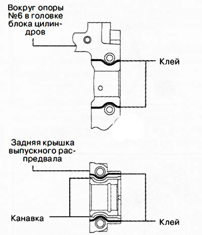
Apply adhesive (Loctite 962T) around support No. 6 of the cylinder head or on the rear cover of the exhaust camshaft.
Attention. Make sure that the adhesive does not get on the camshaft journal.
Note: Adhesive bead width: 0.5-1.5 mm.
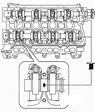
Install the camshaft covers in numerical order (according to the markings on the lids) and evenly screw on the cover bolts in two or three passes in the sequence shown in the figure.
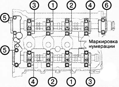
Tighten the camshaft cover bolts in two stages in the sequence shown in the figure: first to a torque of 3.0-6.0 Nm, and then to a torque of 8-11 Nm.
6. Screw in the oil control valve.
7. Install the electric valve timing:
Remove the rope that hangs the drive chain on the intake side.
Remove the drive chain from the exhaust and intake camshaft sprockets and move back, then insert the electric valve timing between the front cover of the engine and the cylinder head.
Return drive chain to exhaust camshaft sprocket.
Aligning the mark on the drive chain, made during removal, with the mark on the electric phase regulator, install the chain on the sprocket.
By aligning the dowel pin on the end of the intake camshaft with the groove on the side of the camshaft adjuster, install the electric camshaft adjuster.
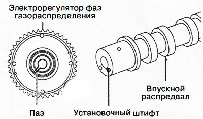
Note: Adjust the relative position of the dowel pin and groove by rotating the camshaft.
Holding the intake camshaft with a wrench by the hexagonal part, tighten the bolt of the electric phase adjuster to a torque of 102-114 Nm.
8. Install damper No. 1 of the drive chain.
9. Remove the tensioner shoe fixing bolt to tension the drive chain.
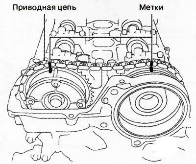
10. Turn the crankshaft two turns clockwise to make sure the timing marks are set correctly.
 |  |
Note: If the timing marks are not set correctly, remove the engine front cover and reinstall the drive chain on each of the sprockets.
11. Install plugs (top and bottom) into the service holes on the front cover of the engine.
Note:
Plug tightening torques:
- top: 8-11 Nm;
- lower: 17-23 Nm.
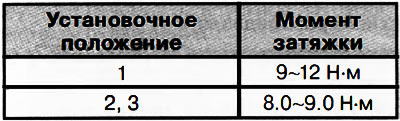
12. Install the oil spray pipes and tighten the mounting bolts in the sequence shown in the figure.
 |  |
13. Install all remaining parts in the reverse order of removal.
14. Start the engine and check its operation.