
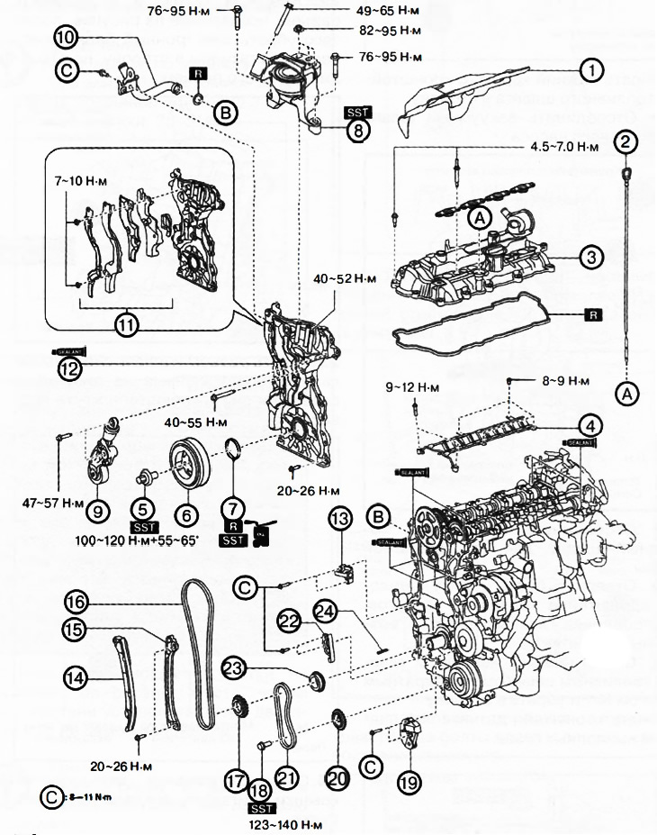
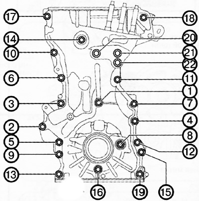
1. Insulating casing.
2. Oil dipstick.
3. Cylinder head cover.
4. Oil spray pipe.
5. Crankshaft pulley bolt.
6. Crankshaft pulley.
7. Front crankshaft oil seal.
8. Mounting support No. 3 of the engine.
9. Automatic tensioner for attachment drive belt.
10. Branch pipe of the cooling system.
11. Soundproof covers (Nos. 1 and 2) with rubber seals.
12. Engine front cover.
13. Timing chain tensioner.
14. Shoe of the timing chain tensioner.
15. Drive chain damper.
16. Timing chain drive.
17. Crankshaft sprocket.
18. Oil pump sprocket bolt.
19. Oil pump drive chain tensioner.
20. Oil pump sprocket.
21. Oil pump drive chain.
22. Oil pump drive chain damper.
23. Oil pump drive sprocket.
24. Key.
Note:
: replace the part with a new one after each removal.
: use a special tool or attachments.
: where to apply the sealant.
: apply oil.
Attention.
- A hot engine can cause burns. Before starting work, turn off the engine and wait until it cools down.
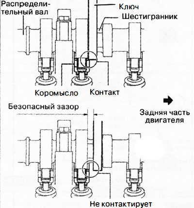
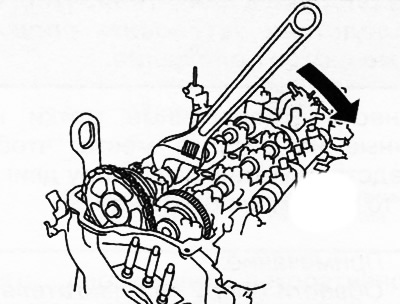
- When turning the camshaft with a wrench on the hex part, the wrench may rest against the rocker and damage it. To prevent damage to the rocker arm, when holding the camshaft by the hex part, place the wrench closer to the rear of the engine, as shown in the figure, to ensure a safe gap between the wrench and the camshaft cam.
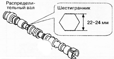
Note: The width of the hex part of the camshaft is 22-24mm.
Removing
1. Disconnect the negative battery terminal.
2. Remove the decorative engine cover.
3. Remove the front protective tray #2.
4. Remove mudguard.
5. Remove attachment drive belts.
6. Drain engine oil.
7. Remove the oil pan.
8. Remove the fuel injectors from the engine.
9. Drain coolant.
10. Remove the insulating casing from the motor.
11. Remove the oil dipstick.
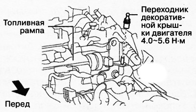
12. Remove pressure fuel line.
13. Remove the high pressure fuel lines (on the supply side of the pump).
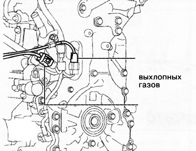
14. Remove wiring to the side:
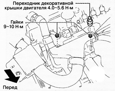
Remove the decorative engine cover adapter and unscrew the nuts shown in the figure.
Disconnect the connectors and clips shown in the figure.
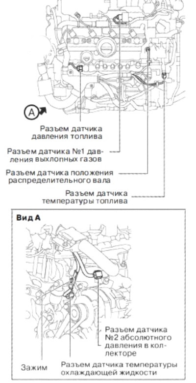
Remove the clips shown in the figure and put the wires aside.
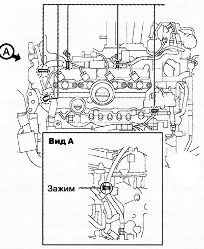
Move the earth cable clip shown in the illustration away from the cylinder head cover.
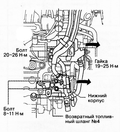
15. Remove the lower housing with the fuel hose bracket to the side:
Disconnect the vacuum hose from the vacuum pump.
Disconnect the #4 fuel return hose from the fuel rail.
Loosen the fuel hose bracket bolts and nut without disconnecting the main hose and return hose #1.
Remove the lower housing with the main fuel hose and return hose No. 1 and set aside.
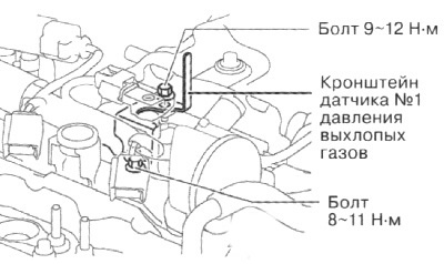
16. Remove the No. 1 exhaust pressure sensor bracket.
17. To remove a cover of a head of the block of cylinders.
18. To turn away bolts of fastening and to remove an oil-spraying tube from a head of the block of cylinders.
19. Unscrew the central bolt and remove the crankshaft pulley.
20. To take a forward epiploon of a cranked shaft from a forward cover of the engine.
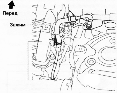
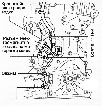
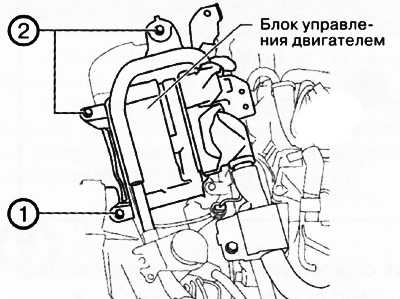
21. Remove the clip and unscrew the bolt shown in the figure, then remove the earth cable to the side.
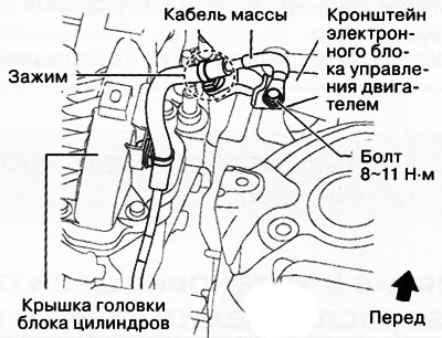
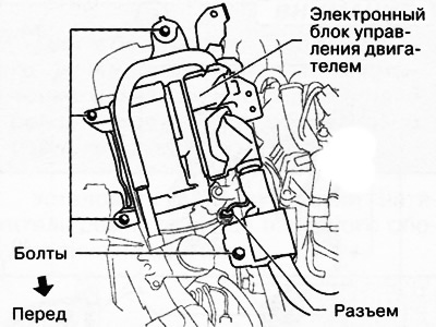
22. Unscrew the bolts and disconnect the connector shown in the figure, then remove the electronic engine control unit to the side without disconnecting the connector from it.
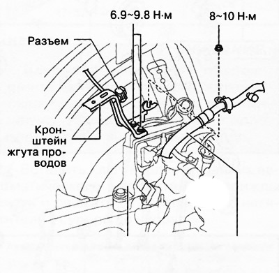
23. Move the connector and coolant hose shown in the figure to the side and remove the wiring harness bracket.
24. Remove the decorative engine cover adapter shown in the figure.
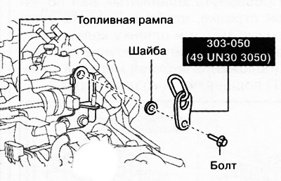
25. Using a bolt with a washer, install the lifting eye on the engine as shown in the figure.
Note:
- Bolt: part number 99794 1025 or M10x1.25, 25 mm long.
- Washer: approx. 3 mm thick.
- Tightening torque: 38-51 Nm.
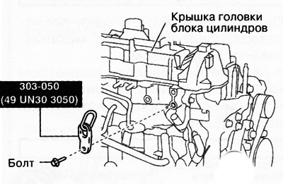
26. Using a bolt and washer, install the second lifting eye on the engine as shown in the figure.
Note:
- Bolt: part number 99794 1025 or M10x1.25, 25 mm long.
- Washer: approx. 3 mm thick.
- Tightening torque: 38-51 Nm.
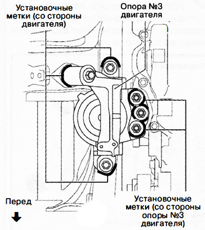
Attention. The grooves must align with the mounting holes of the motor mount #3. If the position of the engine support No. 3 during reinstallation differs from the original position, this will lead to increased noise and vibration of the engine. Before removing engine mount #3, make alignment marks on engine mount #3 to set the mount to the same position later.
27. Apply alignment marks to the places indicated in the figure in order to subsequently install the engine support in the same position.
Note: Outline motor mount #3 and mounting nuts as shown.
28. Install the traverse for hanging the engine 49 C017 5A0:
Attention. Follow the instructions supplied with the crosshead by the manufacturer.
Note: Install #2 front legs on the left and right traverse support rods.
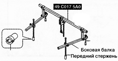
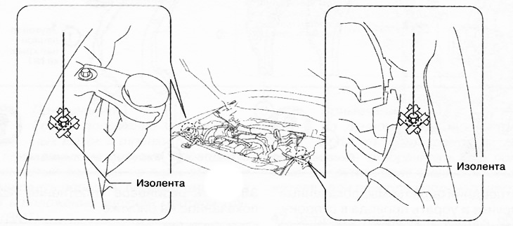
Protect the areas indicated in the figure with electrical tape.
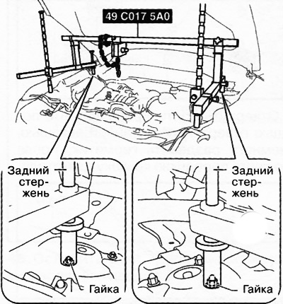
Place the rear yoke support rods on the left and right suspension strut nuts as shown in the illustration.
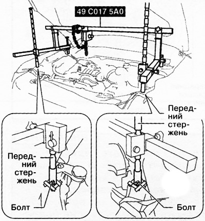
Install the front traverse rods on the bolts on the left and right, as shown in the figure.
Adjust the height of the left and right side beams of the traverse so that they are even, and then tighten all parts.
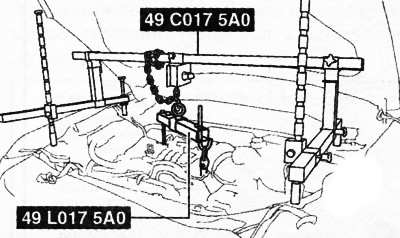
Install suspension bracket (49 L017 5A0) to the traverse (49 UN30 3050), with the hanger hooks pointing outward.
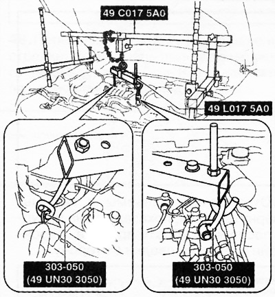
Adjust the height of the left and right side beams of the traverse so that they are even, and then tighten all parts.
Tighten the chain connecting the yoke to the engine.
29. Remove support No. 3 of the engine.
30. Remove the automatic attachment drive belt tensioner (see relevant section earlier in this chapter).
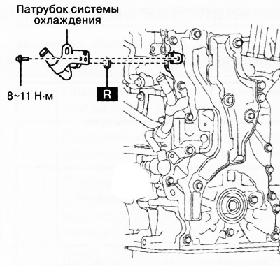
31. Unscrew the fastening bolt and remove the cooling system pipe with the hose connected, and then put it aside.
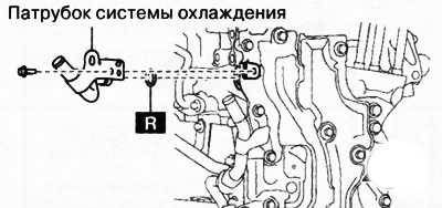
Note:: replace the part with a new one after each removal.
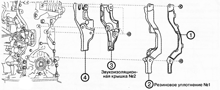
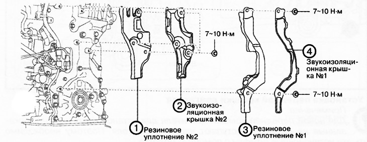
32. Remove soundproof covers (Nos. 1 and 2) with rubber gaskets in the sequence shown in the figure.
33. Disconnect the connectors shown in the figure and put the wires aside.
34. To turn away a bolt of fastening of a branch pipe of system of cooling shown in drawing.
35. Disconnect the connectors and clamps, unscrew the bolts shown in the figure, then remove the wires and the wiring bracket to the side.
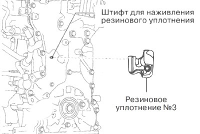
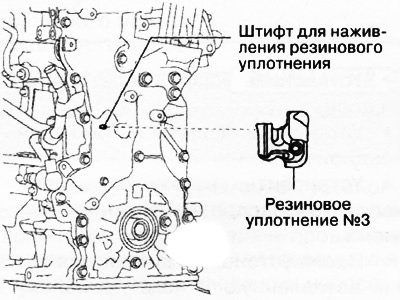
36. Remove the #3 rubber seal shown in the illustration.
37. Loosen the mounting bolts and use a screwdriver wrapped in rags to gradually separate the sealant, then remove the engine front cover.
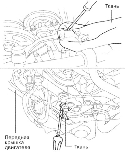
Attention.
- Do not apply excessive force to the screwdriver. Otherwise, the engine front cover may be damaged.
- Be careful not to scratch or damage the contact surfaces. Otherwise, it may cause oil leakage.
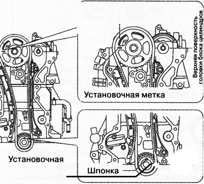
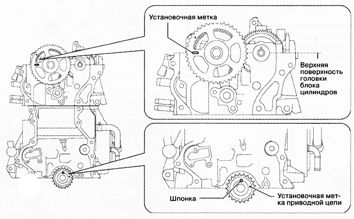
38. Turn the crankshaft clockwise to set the alignment marks and the crankshaft key to the position shown in the figure (top dead center position (TDC) piston of the first cylinder).
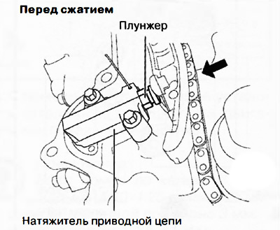
39. Loosen the timing chain tensioner as follows:
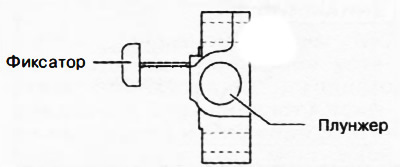
Insert a wire with a diameter of about 1.4 mm or folded paper into the hole in the timing chain tensioner housing.
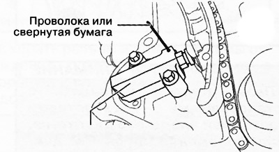
While moving the exhaust camshaft with a hexagon wrench in the direction of the arrow in the figure, press in the timing chain tensioner plunger.
Note: Turning the exhaust camshaft clockwise tightens the drive chain slightly, which pushes the tensioner plunger in.
 | 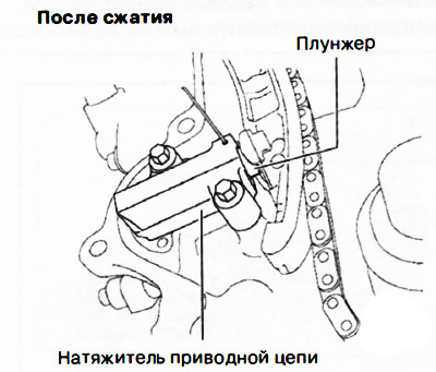 |
With the plunger depressed, pass the wire or folded paper inserted earlier into the tensioner body even further.
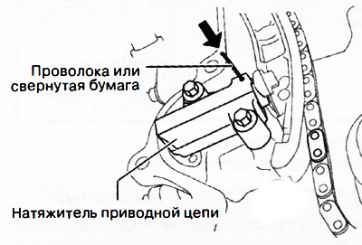
Note: Wire or rolled paper will hold the plunger, which will relieve tension on the drive chain.
40. Remove the drive chain tensioner with tensioner shoe.
41. Remove the damper for the timing chain.
42. Remove the timing chain.
43. Remove the sprocket from the crankshaft.
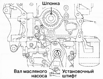
44. Make sure that the alignment marks of the oil pump drive sprockets and the key are in the positions shown in the figure.
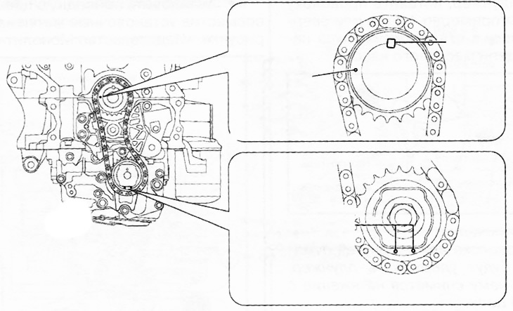
Note: If the position of the alignment marks and key is different from those shown in the figure, turn the crankshaft one more turn and set the piston of the first cylinder No. 1 to the top dead center position (TDC).
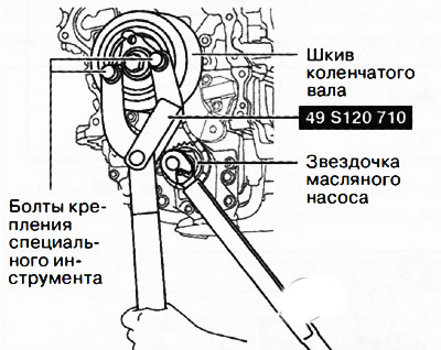
45. Temporarily screw in the crankshaft pulley bolt and hold the oil pump from turning as shown in the figure.
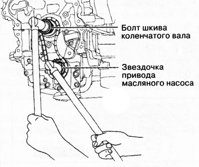
46. Loosen the oil pump sprocket bolt.
Note: At this stage, you only need to loosen the sprocket mounting bolt, but do not completely unscrew it. Remove the bolt after removing the oil pump drive chain tensioner.
47. Insert a flat screwdriver wrapped with a cloth into the gap between the protrusion on the bottom of the cylinder block and the oil pump chain, as shown in the figure.
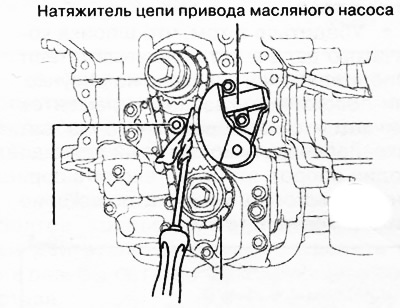
48. While moving the screwdriver in the direction of the arrow, press the oil pump drive chain and push in the oil pump drive chain tensioner plunger.
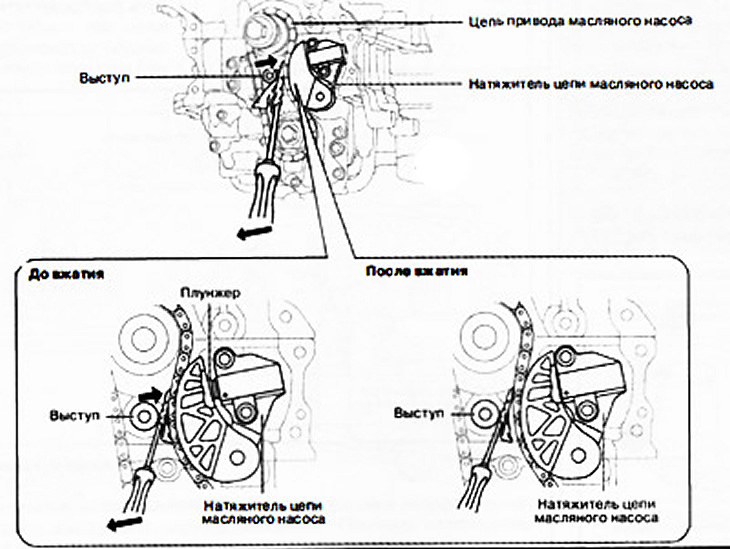
49. While pressing the plunger, insert a wire with a diameter of approximately 1.4 mm or folded paper into the hole in the oil pump chain tensioner housing.
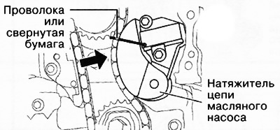
Note: Wire or rolled paper will hold the plunger, which will relieve tension on the drive chain.
50. Remove the oil pump chain tensioner.
51. Remove the drive chain with the oil pump sprocket in one assembly.
52. Remove the temporarily installed crankshaft pulley bolt.
53. Remove the key from the crankshaft.
Installation
1. Installation is carried out in the reverse order of removal, taking into account the following:
Installing the oil pump drive chain
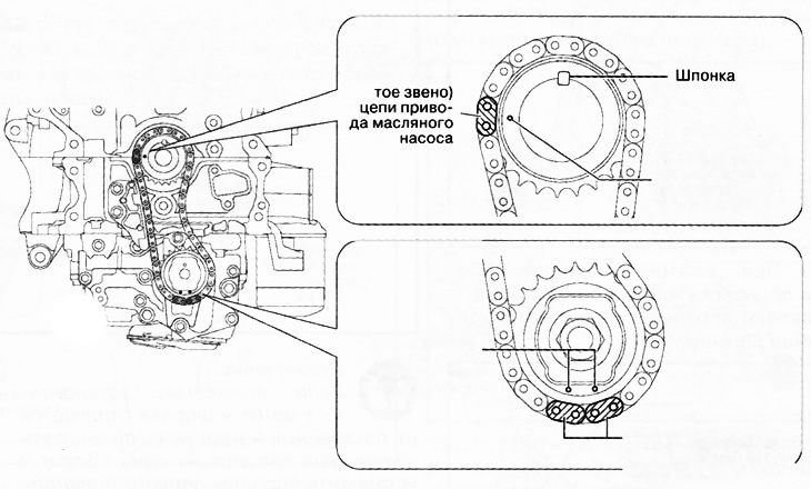
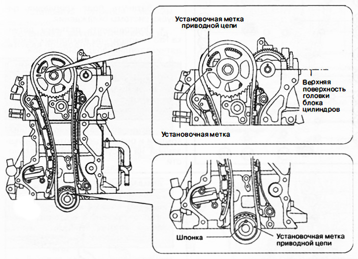
Make sure the crankshaft key and dowel pin are positioned as shown. If the position of the indicated elements differs from that shown in the figure, turn the crankshaft one more turn to set the piston of the first cylinder to the top dead center position.
Note: To rotate the #1 balance shaft, temporarily install the oil pump sprocket, then rotate while holding the sprocket with your hand.
Align the timing marks on the timing chain with those on the oil pump sprocket.
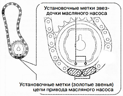
Install the drive chain with the oil pump sprocket in one unit, aligning the timing marks on the sprockets and the drive chain as shown in the figure.
Install the oil pump sprocket bolt.
Install the oil pump drive chain tensioner.
Attention. At this stage, do not remove the wire or rolled paper inserted into the tensioner body.
Install the crankshaft pulley and temporarily screw in the center bolt, then install the special tool shown in the figure to block the oil pump from turning. Tighten the oil pump sprocket bolt to 123-140 Nm.
Unscrew the temporarily installed central bolt and remove the pulley from the crankshaft. Remove the wire or folded paper inserted into the hole in the oil pump housing.
Note: If using a new drive chain tensioner, remove the installed retainer.
Installing the timing chain
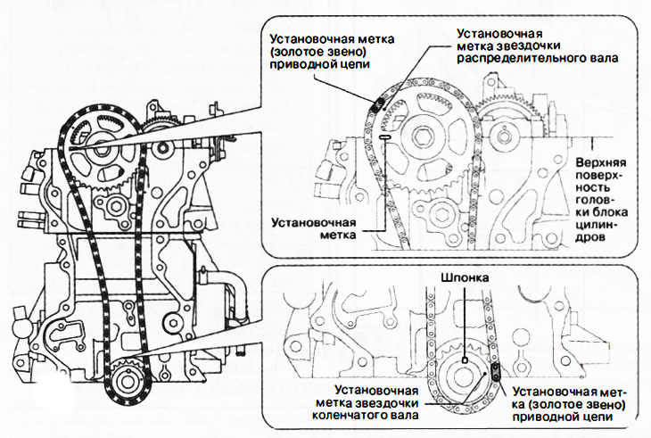
Make sure that the timing marks and crankshaft key are located as shown in the illustration. If the location of the alignment marks differs from the specified one, turn the camshafts and crankshafts so that the piston of the first cylinder is at top dead center (TDC).
Install the timing chain, aligning the sprocket and timing chain marks as shown in the illustration.
Install the drive chain guide.
Install the drive chain tensioner shoe.
Install the timing chain tensioner.
After installing the tensioner, remove the wire or rolled paper inserted into it, and then apply tension to the drive chain.
Note: If using a new drive chain tensioner, remove the installed retainer.
Check for slack in the timing chain and recheck the alignment marks on all sprockets.
Turn the crankshaft two turns clockwise and check the position of all alignment marks again.
Installing the engine front cover
Note: For a new engine front cover, the two locating pins shown in the illustration protrude outside of the engine. Therefore, it is necessary to drive in these dowel pins with a hammer.
 | 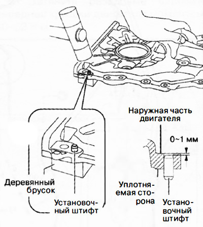 |
Remove oil, dirt and sealant residues from the contact surfaces of the engine front cover, cylinder head and cylinder block.
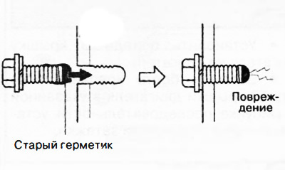
When reusing the bolts of the front cover of the engine, it is necessary to remove the remnants of the fixing composition from their threads.
Attention.
- Apply silicone sealant in an even, continuous bead.
- To prevent premature curing of the silicone sealant, install the front cover on the engine within 10 minutes of applying the sealant. Tighten the fastening bolts immediately.
- If the bolt with hardened sealant is tightened, it may cause a crack in the cylinder head or cylinder block.
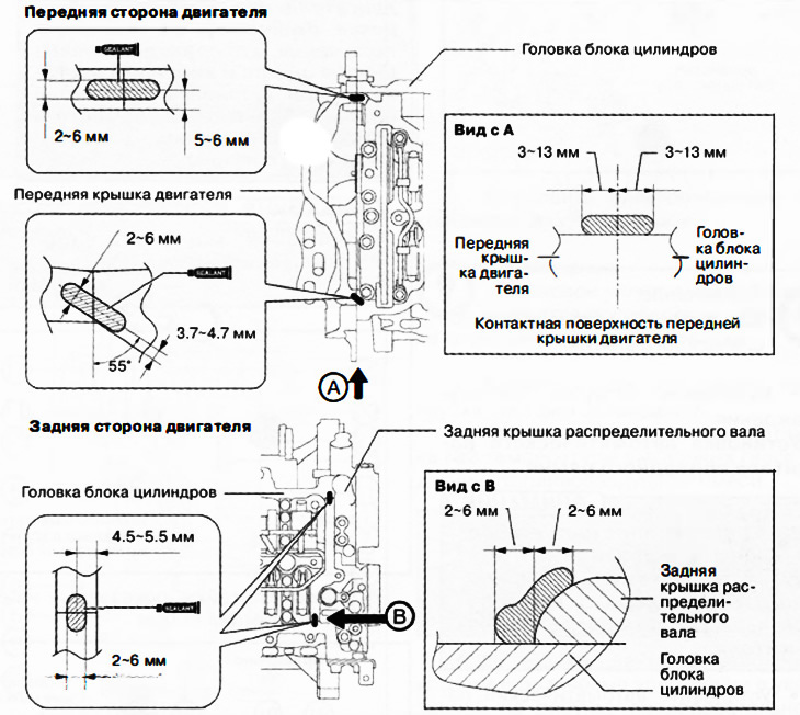
Apply silicone sealant as shown.
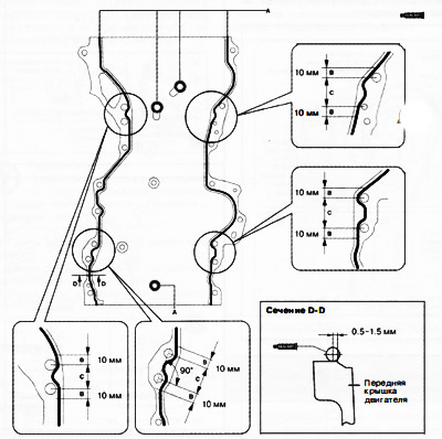
A: 2-6 mm, B: 4-6 mm, C: 4-8 mm.
Apply sealant also to the areas indicated in the following figure.
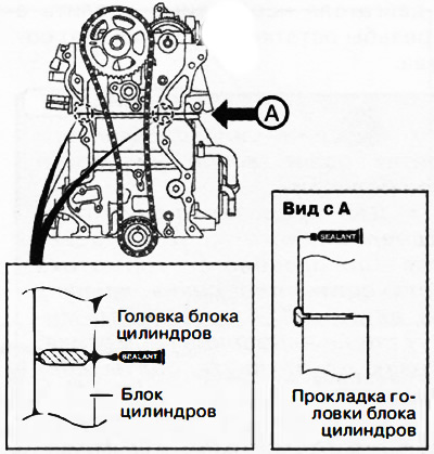
Attention. Apply silicone sealant so that it enters the cylinder head gasket.
Install the engine front cover to the engine.
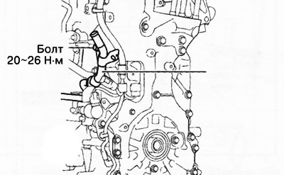
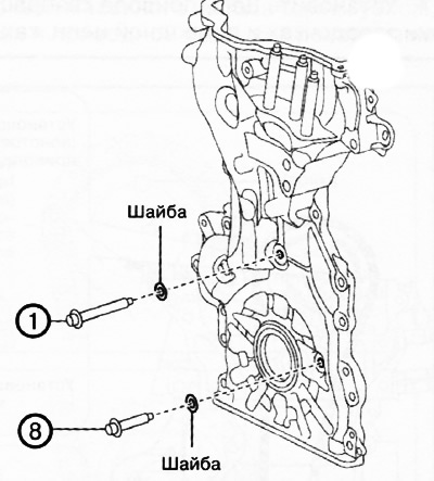
Tighten the engine front cover bolts in the sequence shown in the figure to the specified tightening torques.
Note:
Tightening torques:
- Bolts 1... 19: 20-26 Nm.
- Bolts 20...22: 40-55 Nm.
Attention. Bolts 1 and 8 (see numbering in the picture), are installed with washers.
 |  |
Installation of soundproof covers (Nos. 1 and 2) with rubber seals
Thread #3 rubber seal onto engine front cover.
Install wiring harness and wiring harness bracket.
Note: #3 rubber seal is fixed by installing the wiring bracket.
Tighten the bolt securing the coolant pipe.
Connect the #3 exhaust gas temperature sensor and air-fuel ratio sensor connectors.
Attention. Make sure that the covers and rubber seals are not pinched by the soundproofing bolts.
Install the soundproof covers and rubber seals in the sequence shown in the figure.
Installation of a branch pipe of the cooling system
Attention.
- Don't apply too little (motor, transmission, etc.) on the O-rings of the water inlet pipe. Otherwise, the material of the O-rings may be damaged, resulting in a leak.
- Install the coolant pipe in such a way that the O-ring is not damaged. Otherwise, the seal will be broken, resulting in leakage.
Apply coolant to the O-ring.
Note:: replace the part with a new one after each removal.
Install the coolant pipe.
Installing the automatic drive belt tensioner
Attention. To ensure proper operation of the automatic drive belt tensioner, it is essential to bleed the air from the tensioner.
Install the automatic attachment drive belt tensioner to the engine.
Attention. To prevent damage to the automatic drive belt tensioner, do not apply excessive force after turning the tensioner all the way.
After inserting a wrench into the drive belt auto-tensioner hex, move the auto-tensioner up and down three times from lock to lock to bleed air from the tensioner.
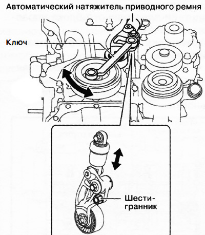
Note: In the process of compressing / unclenching the automatic tensioner from lock to lock, the piston inside the tensioner moves, expelling air.
Installing Engine Mount #3
Attention. If the position of the engine support No. 3 during reinstallation differs from the original position, this will lead to increased engine noise and vibration. When installing engine mounting support No. 3, align the alignment marks made before removal.
Note:
- In case of replacing engine mounting support No. 3, transfer the marks on the new part to the same places that were marked before removing the old mounting support.
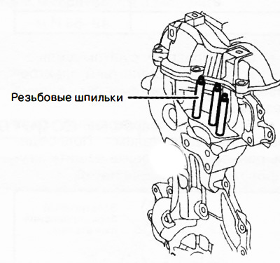
- If the #3 engine mount nuts are loose, the engine front cover threaded studs must be retightened as they may be loose, not the nuts.
Tighten the threaded studs on the engine front cover to 40-52 Nm.
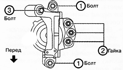
Align the alignment marks as shown in the figure and install the bolts.
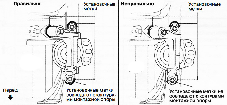
Install the nuts shown in the figure, aligning them with the alignment marks of the mounting support.
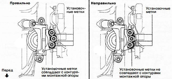
Note: If the alignment marks do not match, align them by moving the motor slightly, then screw on the nuts.
Tighten the #3 engine mount bolts and nuts in the order shown in the illustration.
 |  |
Remove the traverse from the vehicle.
Install the wiring bracket, coolant hose and connectors.
Install the electronic engine control unit. Connect the connector and install the wire harness guard.
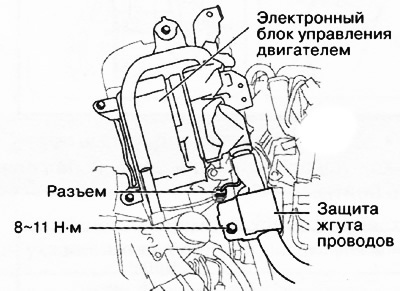
Install the screws shown in the figure.
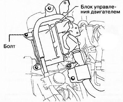
Tighten the bolts of the electronic engine control unit in the sequence shown in the figure with a tightening torque of 9-10 Nm.
Install the earth cable to the bracket of the electronic engine control unit.
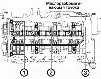
Installing the oil spray pipe
Install the oil spray pipe and tighten the mounting bolts in the sequence shown in the figure.
 |  |
Installing the cylinder head cover
Attention.
- To ensure the tightness of the cylinder head cover, the following must be observed:
- Make sure the cylinder head cover gasket is inserted into the cover groove and install the cylinder head cover.
- Remove oil, dirt and sealant residues from the contact surfaces.
- To prevent premature curing of the silicone sealant, install the cylinder head cover on the engine within 70 minutes of applying the sealant and tighten the mounting bolts immediately.
Insert a new gasket into the groove of the cylinder head cover.
Apply silicone sealant to the areas shown in the illustration.
Fit the two screws shown in the figure.
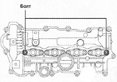
Tighten bolts A in the sequence shown in the figure to a torque of 4.5-7.0 Nm.
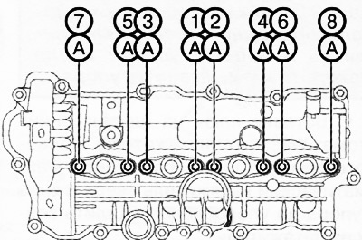
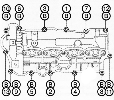
Tighten bolts B in the sequence shown in the figure to a torque of 4.5-7.0 Nm.
Installation of the insulating casing
Position the front edge of the insulating cover so that it is located towards the front of the vehicle relative to the exhaust manifold insulator.
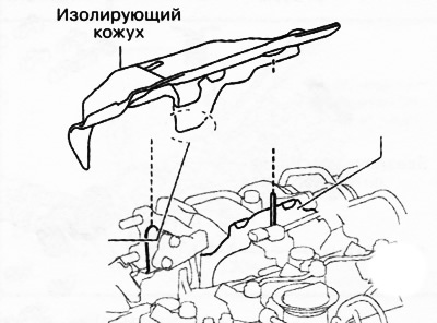
Insert the insulating cover up to the stop.
Actions after installing all engine components
Fill in the required amount of engine oil.
Refill coolant.
Check the tightness of the engine cooling system.
Start the engine and check:
- The presence of engine oil leaks.
- Engine oil level.
- Runout and grazing of pulleys and drive belt.
- Engine idle speed.