
Place the hydraulic lifter in the engine oil reservoir.
Attention. Do not insert the rounded rod with great force as the check valve ball spring is extremely weak.
Lightly pressing the check valve ball with a rounded rod (about 1.0 mm in diameter), remove the air by moving the plunger up and down.
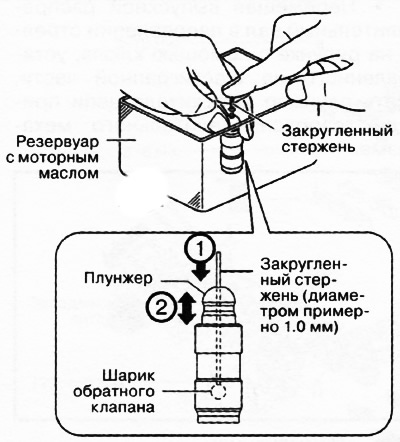
Press the end of the plunger into the oil and make sure there is no pushing sensation. Otherwise, it is necessary to replace the hydraulic compensator with a new one.
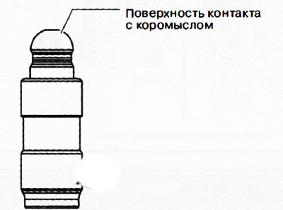
2. Visually inspect the surface of the hydraulic lifter in contact with the rocker arm for wear or damage. If any defects are found, replace the gyro compensator with a new one.
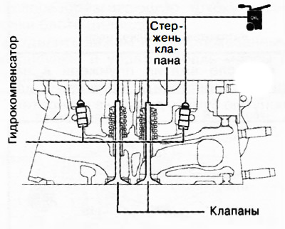
3. Install the hydraulic compensator in its original position in the cylinder head.
4. Apply engine oil to the hydraulic lifters and the ends of the valve stems, then set the rocker arms to their original positions, which they occupied before removal.
Note:apply oil.
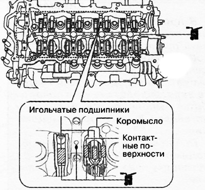
5. Apply gear oil (SAE 90 or similar) or engine oil on the following areas:
- Each support in the cylinder head.
- Needle bearings and rocker contact surfaces.
Note:apply oil.
6. Apply gear oil (SAE 90 or similar) or engine oil on the following surfaces of each camshaft:
- Gear contact surfaces.
- Thrust surfaces of the anterior neck
Note: When applying oil to the front camshaft cover, do not apply oil to the thrust surface of the front camshaft journal.
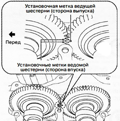
7. Place the camshafts in the cylinder head and align the gear alignment marks as shown.
8. Apply gear oil (SAE No. 90 or similar) or engine oil on the center of each camshaft journal as shown.
Note:apply oil.
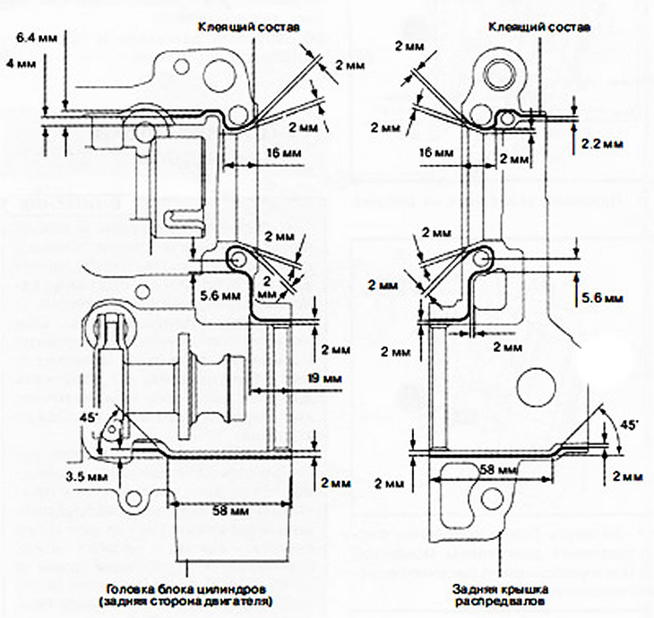
9. Apply adhesive (Loctite 962T) on the rear side of the cylinder head or on the rear camshaft cover.
Attention.
- Make sure that the adhesive does not get on the camshaft journal.
- To prevent premature curing of the adhesive, install the rear camshaft cover and cylinder head within 10 minutes of application. Tighten the fastening bolts immediately.
Note: Adhesive bead width: 1.0-3.0 mm.
10. Apply engine oil to a new O-ring and install it in the rear camshaft cover.
Attention. Be careful not to damage or drop the O-ring when installing the rear camshaft cover.
11. Apply gear oil (SAE 90 or similar) or engine oil on the thrust surface of the front camshaft cover.
Note: If oil is applied to the thrust surface of the front journal of each camshaft, it is not necessary to apply oil to the front cover of the camshafts.
12. Install the camshaft covers in numerical order (according to the markings on the lids) and evenly screw on the cover bolts in two or three passes in the sequence shown in the figure.
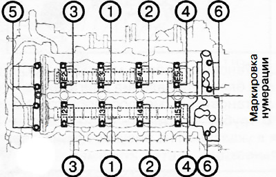
13. Tighten the camshaft cover bolts in two stages in the sequence shown in the figure:
- Stage 1: 3.0-6.0 Nm.
- Stage 2: 8-11 Nm.
14. Pulling the drive chain with the camshaft sprocket, remove the rope with which they were tied to the bolt in the block head.
15. Align the dowel pin on the end of the exhaust camshaft with the groove in the camshaft sprocket and install the sprocket.
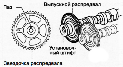
Note: Align the locating pin with the groove by turning the camshaft in the desired direction.
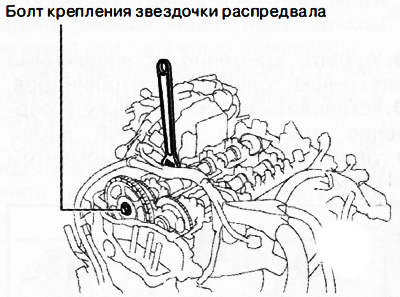
16. Tighten the camshaft sprocket bolt:
- Install the camshaft sprocket mounting bolt.
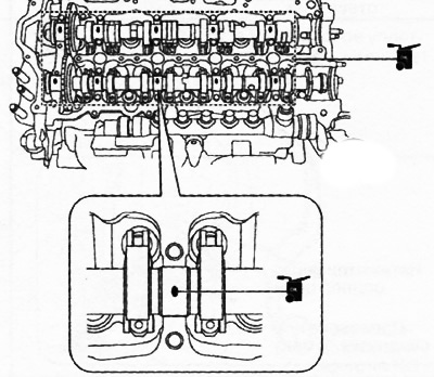
- Holding the exhaust camshaft by the hex part with an adjustable wrench, tighten the camshaft sprocket bolt to 123-140 Nm.
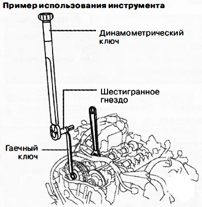
Note: If no suitable tool is available to tighten the camshaft sprocket bolt to the specified torque, the method shown in the figure can be used. In this case, it is necessary to take into account the additional shoulder created by the length of the additional wrench.
17. Remove the wire or rolled paper securing the drive chain tensioner plunger to tension the timing chain.
18. Turn the crankshaft clockwise two turns and check that all timing marks match.
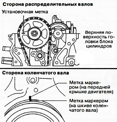
Note: If the timing marks are not set correctly, remove the engine front cover and reinstall the drive chain on each of the sprockets.
19. Remove the temporarily installed cylinder head cover bolt.
20. Install a new plug in the service hole of the engine front cover and tighten to 8-11 Nm.
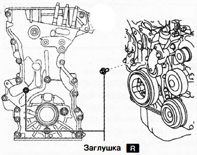
Note:replace the part with a new one after each removal.
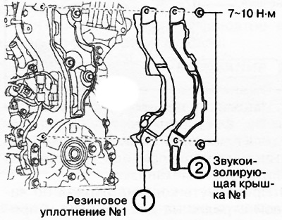
Attention. Make sure that the covers and rubber seals are not pinched by the soundproofing bolts.
21. Install the soundproof cover with rubber seal in the sequence shown in the figure.
22. Install the engine control unit as follows:
Connect the connector and install the wire harness guard.
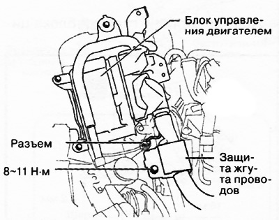
Install the screws shown in the figure.
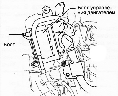
Tighten the engine control unit mounting bolts to 9-10 Nm in the sequence shown in the figure.
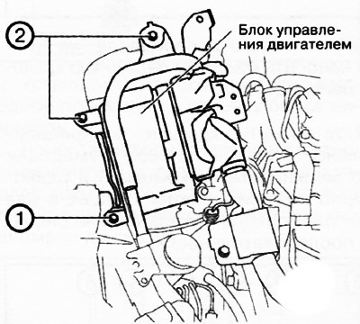
23. Install the ground cable on the engine control unit bracket.
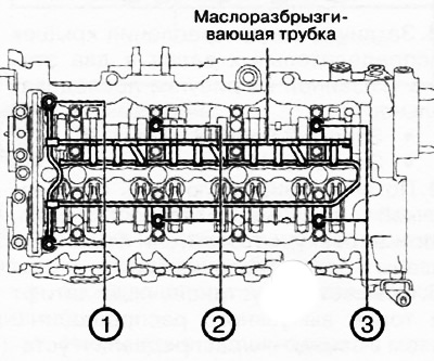
24. Install the oil spray pipe and tighten the mounting bolts in the sequence shown in the figure.
 |  |
25. Install the remaining engine components in the reverse order of removal.
26. Start the engine and check the idle speed.