
Attention.
- A hot engine can cause burns. Before starting work, turn off the engine and wait until it cools down.
- If the camshaft is rotated after the timing chain has been removed, when the piston is at top dead center, the valves may hit the piston crown, causing engine damage. When rotating the camshaft with the drive chain removed, it is necessary to set all the engine pistons to the middle position.
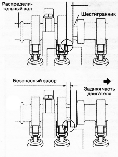
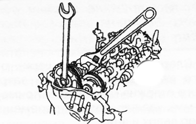
- When turning the camshaft with a wrench on the hex part, the wrench may rest against the rocker and damage it. To prevent damage to the rocker arm, when holding the camshaft by the hex part, place the wrench closer to the rear of the engine, as shown in the figure, to ensure a safe gap between the wrench and the camshaft cam.
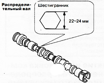
Note: The width of the hex part of the camshaft is 22-24mm.
Removing
1. Disconnect the negative battery terminal.
2. Remove the decorative engine cover.
3. Remove the fuel injectors.
4. Remove the lower housing.
5. Remove the vacuum pump.
6. Remove the supply fuel pump.
7. Remove the cylinder head cover.
8. Remove the camshaft position sensor.
9. Remove mudguard.
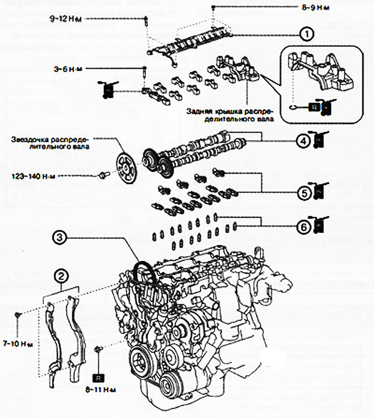
1. Oil spray pipe.
2. No. 1 soundproof cover with rubber seal.
3. Timing chain drive.
4. Camshafts.
5. Rocker arms.
6. Hydraulic gap compensators.
Note:
: replace the part with a new one after each removal.
apply oil.
10. To turn away bolts of fastening and to remove an oil-spraying tube from a head of the block of cylinders.
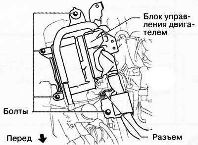
11. Remove the clamp and bolt shown in the figure and put the earth cable aside.
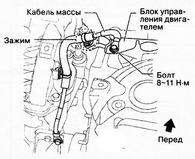
12. Unscrew the bolts and disconnect the connector shown in the figure, then remove the engine control unit to the side without disconnecting the wires from it.
13. Remove soundproof cover No. 1 with rubber seal in the sequence shown in the figure.

Attention.
- During and after work, the drive chain must be kept lifted away from the sprockets. If the chain falls down, it may come off the crankshaft sprocket, and as a result, you will need to perform the entire valve timing installation procedure.
- After completing the work, it is imperative to check the installation of the gas distribution phases.
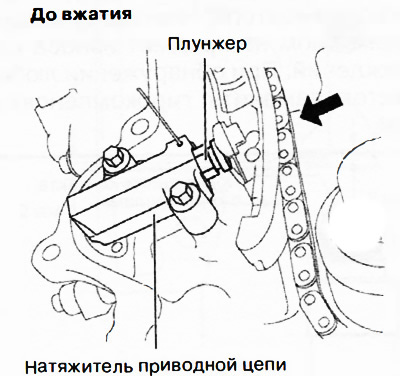
14. Loosen the timing chain tension as follows:
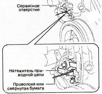
Note: Loosen the tension of the timing chain by fixing the plunger on the timing chain tensioner through the service hole in the front cover of the engine.
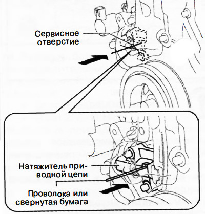
Remove the plug from the service hole in the engine front cover.
Note:replace the part with a new one after each removal.
Insert a wire with a diameter of about 1.4 mm or folded paper into the hole in the timing chain tensioner housing through the service hole.
Note: Before pushing in the drive chain tensioner plunger, insert a piece of wire or folded paper approximately 22.5mm into the engine front cover.
While moving the exhaust camshaft in the direction of the arrow in the figure, using a wrench installed on the hex part, press the plunger of the timing chain tensioner.
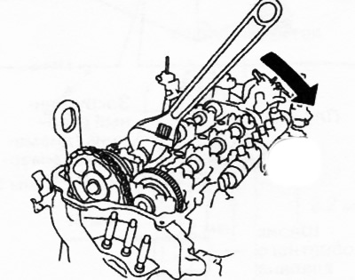
Note: Turning the exhaust camshaft clockwise will tighten the timing chain slightly, pushing the plunger into the tensioner.
 | 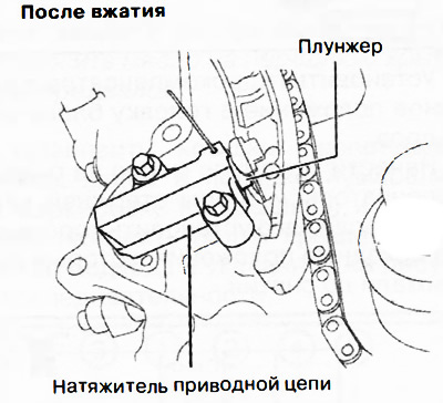 |
After pressing the plunger into the tensioner, deliver the wire or rolled paper further into the hole.
Note:
- When the plunger of the drive chain tensioner is pressed in, the wire or rolled paper can be advanced by about 8 mm.
- Wire or rolled paper holds the plunger in the depressed position, thereby relieving tension in the drive chain.
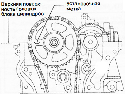
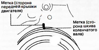
15. Turn the crankshaft clockwise so as to set the piston of the first cylinder to the top dead center position according to the marks shown in the figure.
16. Mark with a marker on the engine front cover and crankshaft pulley to correctly adjust the valve timing during subsequent assembly.
Note: The location of the mark with the marker does not matter. The best would be a label that allows you to check the installation of the valve timing after assembling the engine.
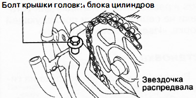
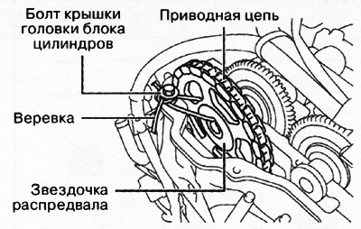
17. Temporarily screw in the cylinder head cover bolt to the position shown in the figure.
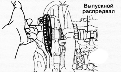
18. Holding the exhaust camshaft by the hex part with an adjustable wrench, unscrew the camshaft sprocket mounting bolt.
19. Disconnect the sprocket from the exhaust camshaft without removing the drive chain from it.
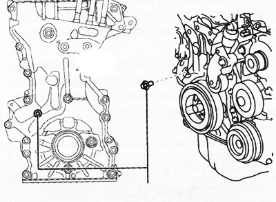
20. Using a rope, tie the camshaft sprocket with the drive chain to the prepared bolt, as shown in the figure.
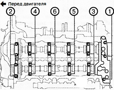
21. In two or three approaches, unscrew the bolts of the camshaft covers in the sequence shown in the figure, and remove the camshaft covers.
22. Remove camshafts.
23. Remove the rocker arms from the cylinder head and lay them out in order for installation in their places during subsequent assembly.
24. Remove the hydraulic clearance compensators from the cylinder head and lay them out in order for installation in their places during subsequent assembly.