


Caution: If the position of engine support No.3 is different from the original position when reinstalling, this will result in increased engine noise and vibration. Before removing engine support No.3, apply alignment marks to engine support No.3 so that the support can be installed in the same position later.
Note: If the engine mounting support #3 fastening nuts are loose, the engine front cover threaded studs must be tightened as they may be loose rather than the nuts.
1. Tighten the threaded studs of the front engine cover to a torque of 40-52 Nm.
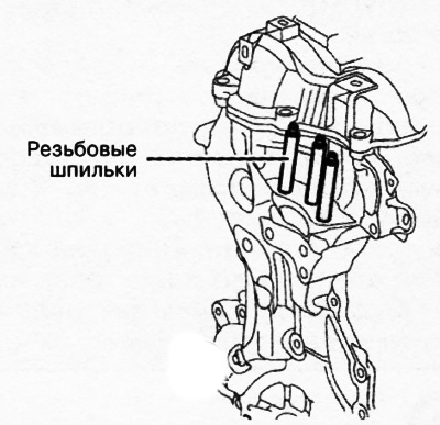
2. Tighten the gearbox threaded studs to a torque of 15-25 Nm.
3. Proceeding in reverse order, place the power unit under the engine compartment of the vehicle, and then lower the vehicle onto the lift.
4. Using an engine lift, raise the power unit to the required height.
5. Tighten the bolts and nuts of mounting support No.3:
Tighten the bolts shown in the figure to center the mounting slots of engine support No.3.
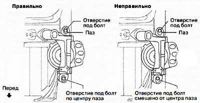
Tighten the nuts shown in the illustration to center the threaded studs of the front engine cover relative to the mounting slots of engine support No.3.
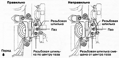
Note: If the threaded studs are offset from the centers of the slots, they must be centered by moving the engine slightly, then tighten the mounting nuts.
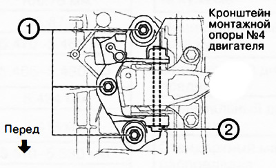
6. Tighten the mounting bolts and nuts of engine mounting support No.4:
Tighten the bolt shown in the figure.
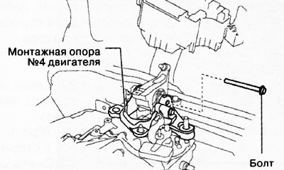
Tighten the nuts shown in the figure to center the slots in the engine mounting support bracket #4.
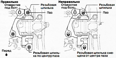
Versions with manual transmission
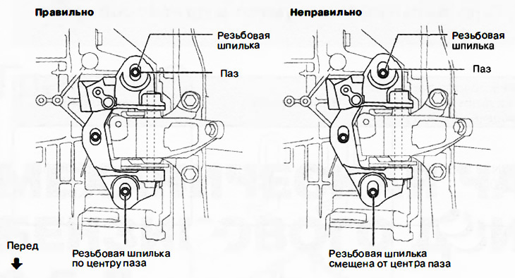
Versions with automatic transmission
Note: If the threaded studs are offset from the centers of the slots, they must be centered by moving the engine slightly, then tighten the mounting nuts.
7. Install the front subframe with engine mounting support cushion No.1 (see chapter "Suspension").
8. Attach the following parts:
Front-wheel drive (2WD) only versions: Engine mount bracket #1, engine mount pad #1 and bracket plate.
The original text is published on: MAZBOOK.ru
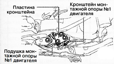
4WD versions: Mounting support pad #1 and bracket plate.
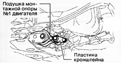
9. Front-wheel drive (2WD) only versions: Tighten engine mount bracket No.1 and bracket plate mounting bolts in the sequence shown in the figure to a torque of 131-153 Nm.
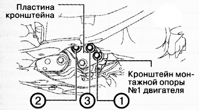
10. Tighten the mounting bolts and nuts of engine mounting support No.3 in the sequence shown in the figure.
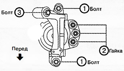 |
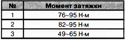 |
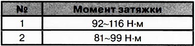
11. Tighten the mounting bolts and nuts of engine mounting support bracket No.4 in the sequence shown in the figure.
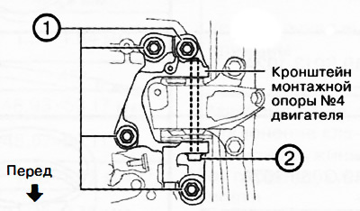
Versions with manual transmission
Versions with automatic transmission
12. Tighten the engine mounting support cushion No.1 mounting bolts.
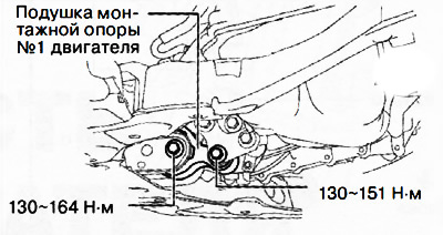
Front-wheel drive (2WD) versions only
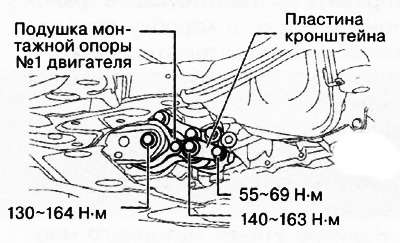
All-wheel drive (4WD) versions
13. Install the sealing plate.
14. Install the wiring bracket, air conditioner hose and connector.
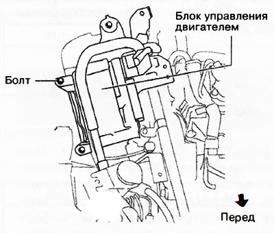
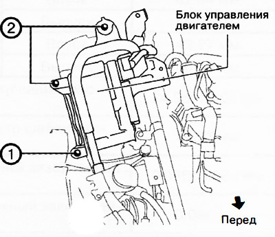
15. Install the electronic engine control unit:
Tighten the bolts shown in the figure.
Tighten the engine control unit mounting bolts in the sequence shown in the figure to a tightening torque of 9-10 Nm.
Install the bolt and connector shown in the figure.
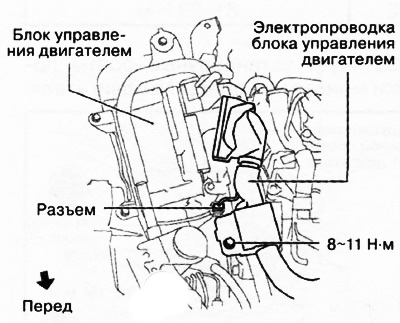
Connect the engine control unit connector (140 conclusions).
16. Fill the gearbox with the appropriate transmission oil (mechanical or automatic).
17. Fill the engine cooling system.
18. Check the wheel alignment angles of the vehicle (see chapter "Suspension").
19. Start the engine and check the following:
- Presence of leaks of engine oil, coolant, transmission oil and fuel.
- Wobbling or binding of pulleys and drive belts.
- Idle speed.
- Functioning of all engine components.
Note: After installing the engine on the vehicle, it is necessary to perform a test drive to ensure that there are no extraneous noises or vibrations.