


2. Remove the decorative engine cover.
3. Remove the air filter with the air duct and air intake assembly.
4. Loosen the bolts and nut and disconnect the connector shown in the figure. Move the wiring aside.
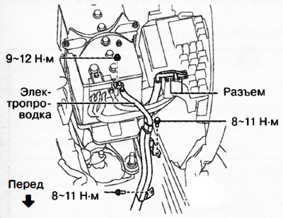
5. Remove the battery from the shelf.
6. Disconnect the ground cables shown in the figure.
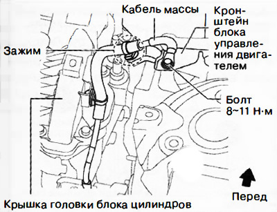
Right side
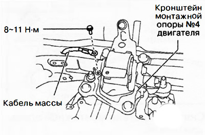
Left side
7. Remove the intake and outlet pipes and hoses of the turbocharger with the intercooler as one unit (intercooler).
8. Drain the coolant from the engine.
9. Drain the transmission oil (versions with manual transmission) or automatic transmission fluid (versions with automatic transmission).
10. Disconnect the gearbox control cable.
11. Versions with manual transmission: remove the clutch slave cylinder without disconnecting the pipes from it.
12. Disconnect the brake booster vacuum hose.
13. Disconnect the main fuel hose and return fuel hose No.1.
14. Disconnect the upper radiator hoses.
15. Disconnect the heater hose.
16. Remove the front wheels from the vehicle.
17. Remove front protective trays No.1 and No.2.
18. Remove the mudguard.
19. If equipped, disconnect the automatic transmission fluid hose from the oil cooler.
20. Disconnect the lower radiator hose.
21. Remove the air-to-air intercooler outlet hose (intercooler).
22. Move the right front fender liner to the side.
23. Remove the air-to-air intercooler outlet pipe (intercooler).
24. Remove the accessory drive belt.
25. Remove the air conditioning compressor without disconnecting the pipes from it and hang it on the body using a rope or wire away from the work.
26. Loosen the fastening nuts of the middle exhaust pipe (from the catalytic converter side) and secure the middle exhaust pipe to the body using a rope or wire away from the work area.
27. All-wheel drive (4WD) versions: remove the propeller shaft.
28. Disconnect the left front drive shaft from the gearbox side and set it aside.
29. Disconnect the right front drive shaft from the gearbox side and set it aside.
30. Loosen the mounting bolts and remove the bracket plate.
31. Loosen the mounting bolt (from the subframe side) engine mounting support cushions No.1, shown in the figure.
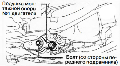
Front-wheel drive (2WD) versions only
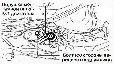
All-wheel drive (4WD) versions
32. Remove the front subframe assembly with the engine mounting support cushion No.1 (see chapter "Suspension").
33. Move the engine control unit with wiring to the side:
- Disconnect the engine control unit connector (140 conclusions).
- Remove the bolt and disconnect the connector shown in the figure and move the wiring towards the top of the engine.
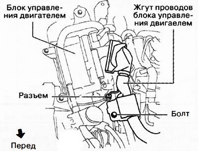
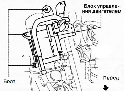
Loosen the bolt shown in the figure and move the engine control unit with the connected connector to the side.
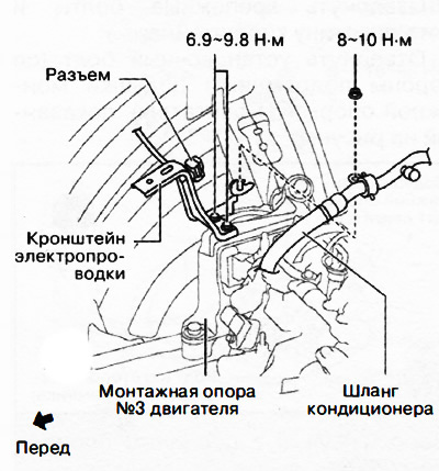
34. Remove the wiring bracket shown in the figure.
35. Remove the sealing plate installed at the bottom of the oil pan.
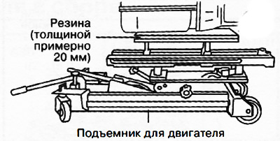
Caution: When supporting the power unit, insert the appropriate size rubber (thickness approximately 20 mm) between the engine jack and the oil pan/gearbox to prevent deformation of the oil pan or damage to the gearbox.
36. Secure the engine with gearbox on a special engine lift.
The text of the article is taken from the website: MAZBOOK.RU
37. Remove engine mounting support bracket No.4.
38. Remove engine mounting support No.3.
39. Raise the vehicle with a lift and roll out the power unit from under the vehicle.
Attention.
- Make sure all connections and connectors are disconnected from the engine.
- Make sure that when lowering the power unit from the engine compartment, it does not catch on various pipes, hoses and wires.