


Attention.
- Hot engine and oil can cause burns. Be careful not to burn yourself when removing/installing various components.
- Fuel vapors are hazardous and flammable, causing serious injury and equipment damage. Keep sparks and open flames away from fuel.
- Leaks and leaks in fuel lines are dangerous. Fuel can ignite and cause equipment damage, serious injury, or even death. Fuel can cause skin and eye irritation. To prevent this, follow safety precautions when handling fuels and lubricants.
Removal the cylinder head
1. Disconnect the negative battery terminal.
2. Remove the decorative engine cover.
3. Remove the fuel injectors.
4. Remove the front engine oil pan No.2.
5. Remove the right mudguard.
6. Remove the accessory drive belt.
7. Drain the engine oil.
8. Drain the coolant.
9. Disconnect the upper radiator hose.
10. Remove the intake manifold.
11. Disconnect the catalytic converter from the middle exhaust pipe and remove the catalytic converter.
12. Remove the turbocharger.
13. Remove the lower housing from the engine.
14. Remove the vacuum pump.
15. Remove the fuel supply pump.
16. Remove the camshaft position sensor.
17. Disconnect the heater hose.
18. Remove the oil pan.
19. Remove the timing chain with the damper (see the relevant section above in this chapter).
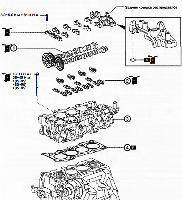
1. Camshafts.
2. Rocker arms.
3. Cylinder head.
4. Cylinder head gasket.
Note:
: replace the part with a new one after each removal.
: apply oil.
20. Loosen the camshaft cover mounting bolts in several steps in the sequence shown in the figure, and remove the camshaft covers.
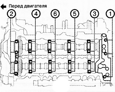
21. Remove the camshafts.
22. Remove the valve rocker arms from the cylinder head and lay them out in order for installation in their places during subsequent assembly.
23. Remove the cooling system hose shown in the figure.
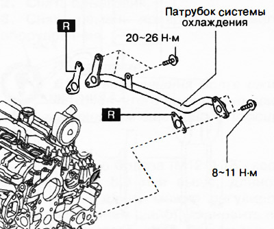
Note:: replace the part with a new one after each removal.
24. Temporarily install an oil pan to support the engine from underneath the vehicle.
Caution: To prevent deformation of the oil pan, support the engine as follows:
- When using an engine lift, place a piece of rubber of appropriate size (thickness approximately 20 mm) between the lift and the oil pan.
- When using a garage jack, place a piece of rubber of the appropriate size (thickness approximately 20 mm) on the support panel resting against the oil pan.
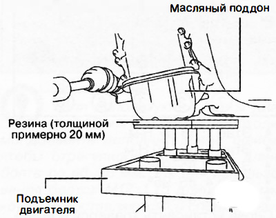
25. Support the engine (oil pan) using a special engine lift or garage jack.
26. Remove the device 49 L017 5A0, on which the engine was suspended, and set it aside.
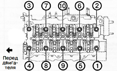
27. Loosen the cylinder head bolts in two or three steps in the sequence shown in the figure.
28. Remove the cylinder head.
29. Remove the cylinder head gasket and replace it with a new one.
Installing the cylinder head
1. Thoroughly clean the contact surfaces of the cylinder block and cylinder head.
2. Install a new cylinder head gasket
3. Install the cylinder head onto the engine.
Caution: If the length (L) of the cylinder head bolt exceeds the maximum permissible value (170.5 mm), it must be replaced with a new one.
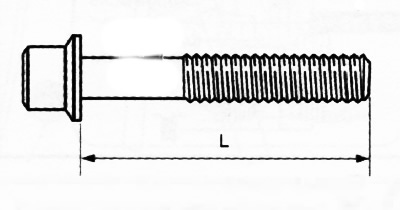
4. If reusing the cylinder head bolts, apply engine oil to their seating surfaces.
5. Tighten the cylinder head bolts in the sequence shown in the figure in five stages:
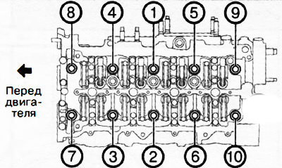
- Stage 1: 13-17 Nm.
- Stage 2: 36-40 Nm.
- Stage 3: 85-95°.
- Stage 4: 85-95°.
- Stage 5: 85-95°.
6. Reinstall the crossmember and hang the engine.
7. Remove the engine lift or garage jack.
8. Remove the temporarily installed oil pan.
9. Apply engine oil to the hydraulic lifters and the ends of the valve stems, then install the rocker arms in the original positions they occupied before removal.
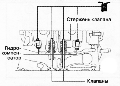
Note:apply oil.
10. Apply transmission oil (SAE 90 or similar) or motor oil to the following areas:
- Each support in the cylinder head.
- Needle bearings and rocker arm contact surfaces.
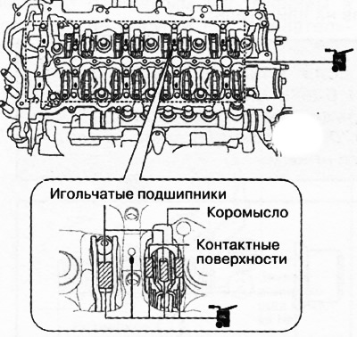
Note:: apply oil.
11. Apply transmission oil (SAE 90 or similar) or engine oil on the following surfaces of each camshaft:
- Contact surfaces of gears.
- Thrust surfaces of the front journal.
Note: When applying oil to the front camshaft cover, do not apply oil to the thrust surface of the front camshaft journal.
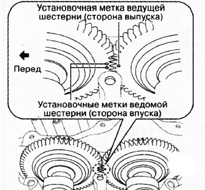
12. Place the camshafts into the cylinder head and align the timing marks on the gears as shown in the figure.
13. Apply transmission oil (SAE No.90 or equivalent) or engine oil to the center of each camshaft journal as shown in the illustration.
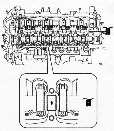
Note:: apply oil.
14. Apply adhesive (Loctite 962T) on the rear side of the cylinder head or on the rear cover of the camshafts.
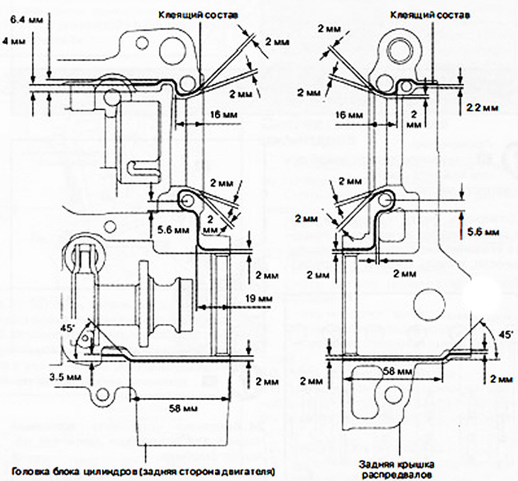
Attention.
- Make sure that no adhesive gets on the camshaft journal.
- To prevent premature hardening of the adhesive, install the rear camshaft cover and cylinder head within 10 minutes of application. Tighten the mounting bolts immediately.
Note: Adhesive bead width: 1.0-3.0mm.
15. Apply engine oil to the new O-ring and install it into the rear camshaft cover.
Caution: Be careful not to damage or drop the O-ring when installing the rear camshaft cover.
16. Apply transmission oil (SAE 90 or similar) or engine oil on the thrust surface of the front camshaft cover.
Note: If oil is applied to the thrust surface of the front journal of each camshaft, there is no need to apply oil to the front camshaft cover.
17. Install the camshaft caps in numbered order (according to the markings on the lids) and evenly tighten the cap bolts in two or three steps in the sequence shown in the figure.
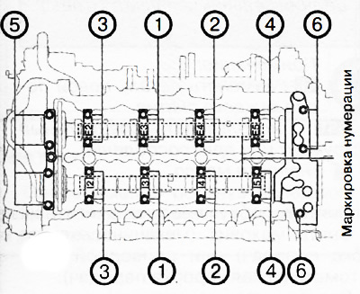
18. Tighten the camshaft cover bolts in two stages in the sequence shown in the figure:
- Stage 1: 3.0-6.0 Nm.
- Stage 2: 8-11 Nm.
19. Install the remaining engine components in the reverse order of removal.
20. Fill with the required amount of engine oil of the required grade (see Chapter 8 "Lubrication system").
21. Fill with coolant.
22. Start the engine and check the following:
- Presence of engine oil and coolant leaks.
- Engine oil level in the engine.
- Beating and touching of pulleys and belts.
- Idle speed.
- Compression in the cylinders.