


Contents: Removal ⇓ Installation ⇓
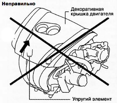
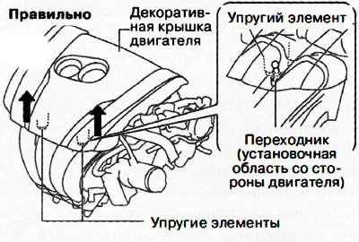
Caution: If the elastic element is lifted only on one side of the decorative engine cover, the locking adapter shown in the figure may be damaged. When removing the decorative engine cover, it is necessary to lift the elastic elements on both sides simultaneously.
 |
 |
Removal
1. While simultaneously pulling the front part of the decorative engine cover, remove the elastic elements from the adapters on the engine.
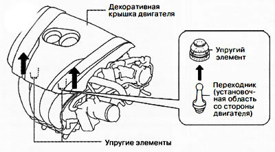
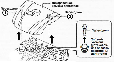
2. Pull the engine decorative cover in the order shown in the figure and remove the adapters from the elastic elements on the engine side.
Installation
Installation is carried out in the reverse order of removal, taking into account the following:
- Press in the rear part of the decorative engine cover in the reverse order of removal.
- Press the front part of the decorative engine cover simultaneously from both sides.