


Contents: Removal ⇓ Installation ⇓
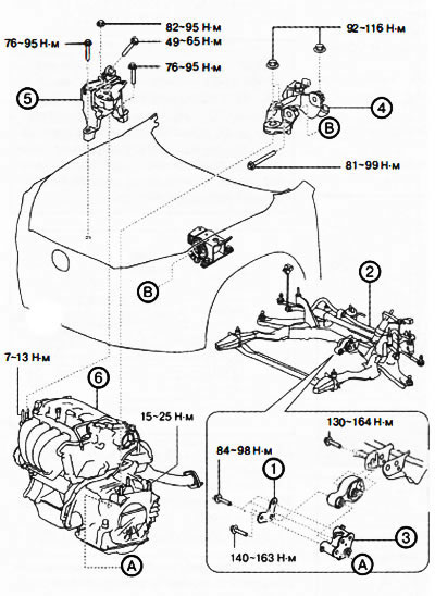
Front-wheel drive (2WD) only versions:
1. Bracket plate.
2. Front subframe with engine mounting support cushion No.1.
Z. Engine mounting support bracket No.1.
4. Engine mounting support bracket No.4.
5. Engine mounting support No.3.
6. Power unit assembly.
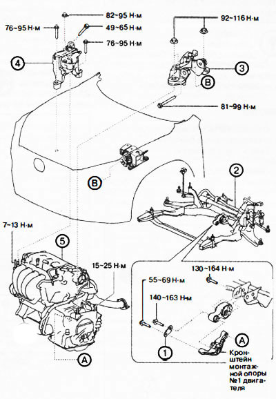
All-wheel drive (4WD) versions:
1. Bracket plate.
2. Front subframe with engine mounting support cushion No.1.
3. Engine mounting support bracket No.4.
4. Engine mounting support No.3.
5. Power unit assembly.
Attention.
- Hot engine and oil can cause burns. Be careful not to burn yourself when removing/installing various components.
- Fuel vapors are hazardous and flammable, causing serious injury and equipment damage. Keep sparks and open flames away from fuel.
- Fix the steering wheel with tape or wire to prevent the steering shaft from turning after disconnecting. If the steering wheel is turned after the steering shaft is disconnected from the steering gear, the internal parts of the contact disk may be damaged.
- Applying excessive force (100 N (10.2 kgf) or more) to the valve timing actuator may cause malfunctions. When servicing, be careful not to damage the valve timing actuator with other parts or tools.
Note: The engine is removed from the vehicle together with the gearbox. Removing/installing the power unit (engine with gearbox assembly) is produced from underneath the vehicle.
Removal
1. Disconnect the negative battery terminal.
2. Remove the decorative engine cover.
3. Remove the air filter with the air duct and air intake assembly.
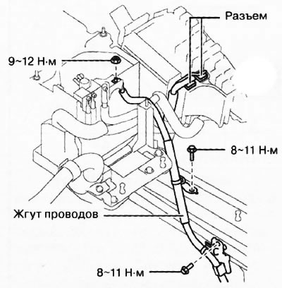
4. Loosen the bolts and nut and disconnect the connector shown in the figure. Move the wiring aside.
5. Remove the battery tray with the vehicle's electrical control unit.
6. Remove front protective trays No.1 and No.2.
7. Remove the mudguard.
8. Drain the coolant.
9. Drain the transmission oil.
10. Remove the front wheels from the vehicle.
11. Disconnect the gearbox control cable.
12. Versions with manual transmission: remove the clutch slave cylinder without disconnecting the hydraulic hose from it.
13. Disconnect the brake booster vacuum hose.
14. Disconnect the fuel vapor recovery system hose.
15. Disconnect the fuel hose.
16. Disconnect the lower and upper radiator hoses.
17. Disconnect the heater hoses.
18. Remove the generator drive belt.
19. Remove the air conditioning compressor without disconnecting the refrigerant lines from it and secure it to the vehicle body using wire or rope to remove it from the engine work area.
20. All-wheel drive (4WD) versions: remove the propeller shaft.
21. Loosen the nuts securing the three-way catalytic converter and secure it to the vehicle body using wire or rope to remove it from the engine work area.
22. Disconnect the left drive shaft from the gearbox side and set it aside.
23. Disconnect the right drive shaft from the gearbox side and set it aside.
24. All-wheel drive versions: remove the right drive shaft.
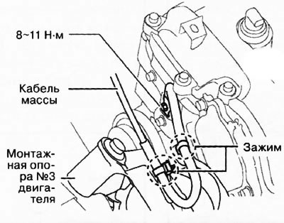
25. Remove the bolts and clamps and move the ground cable to the side.
Right side
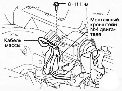
Left side
26. Loosen the mounting bolts and remove the bracket plate.
27. Loosen the mounting bolt (from the subframe side) engine mounting support cushions No.1, shown in the figure.
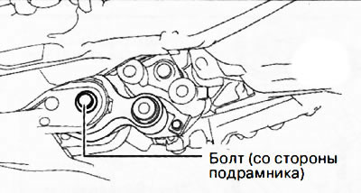
Front-wheel drive (2WD) versions only
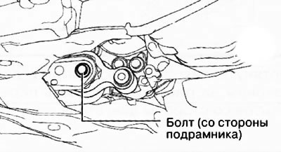
All-wheel drive (4WD) versions
28. Remove the front subframe assembly with engine mounting support cushion No.1 (see Chapter 16 "Suspension").
[Article is available on the website MAZBOOK.RU]
Caution: When supporting the power unit, insert the appropriate size rubber (thickness approximately 20 mm) between the engine jack and the oil pan/gearbox to prevent deformation of the oil pan or damage to the gearbox.
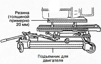
29. Secure the engine with gearbox on a special engine lift.
30. Remove engine mounting support bracket No.4.
31. Remove engine mounting support No.3.
32. Raise the vehicle with a lift and roll out the power unit from under the vehicle.
Attention.
- Make sure all connections and connectors are disconnected from the engine.
- Make sure that when lowering the power unit from the engine compartment, it does not catch on various pipes, hoses and wires.
Installation
1. Proceed in reverse order to place the power unit under the engine compartment of the vehicle, and then lower the vehicle onto the lift.
Caution: If the position of engine support No.3 is different from the original position when reinstalling, this will result in increased engine noise and vibration. Before removing engine support No.3, apply alignment marks to engine support No.3 so that the support can be installed in the same position later.
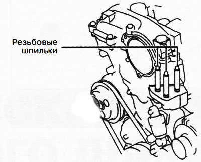
2. Screw the threaded studs into the front engine cover and tighten to a torque of 7-13 Nm.
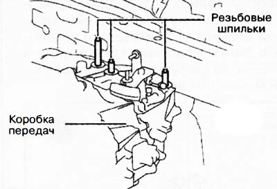
3. Screw the threaded studs into the gearbox and tighten to a torque of 15-25 Nm.
4. Using an engine lift, raise the power unit to the required height.
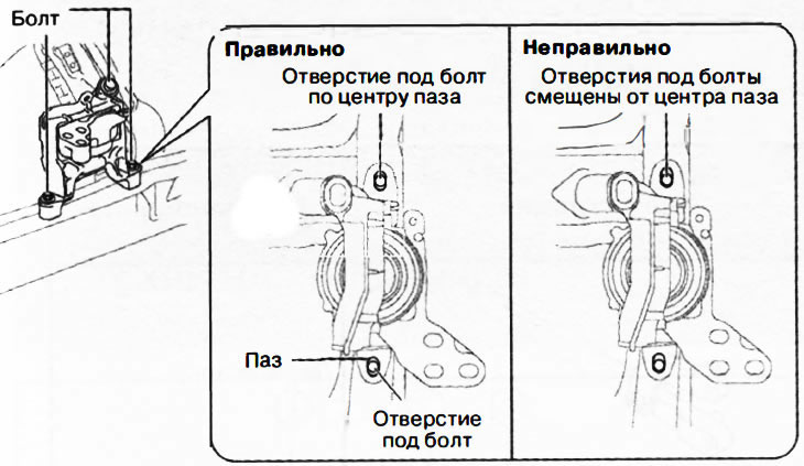
5. Tighten the bolts and nuts of the mounting support 3:
Tighten the bolts shown in the figure to center the mounting slots of engine support No.3.
 |
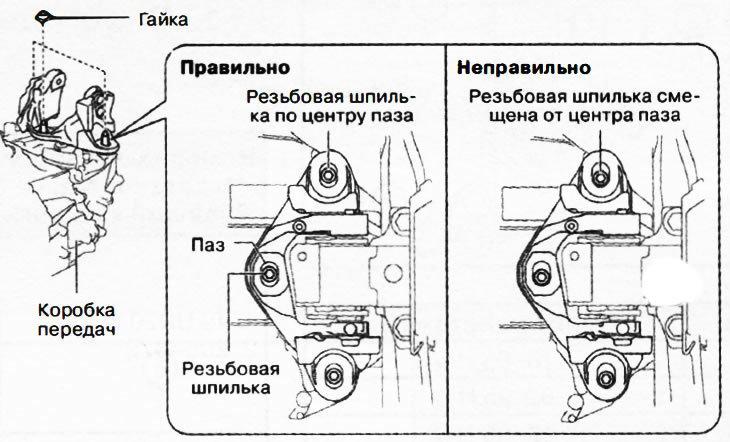 |
Tighten the nuts shown in the illustration to center the threaded studs of the front engine cover relative to the mounting slots of engine support No.3.
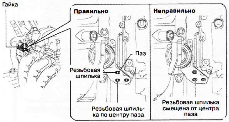
Note: If the threaded studs are offset from the centers of the slots, they must be centered by moving the engine slightly, then tighten the mounting nuts.
6. Tighten the mounting bolts and nuts of engine mounting support No.4:
Tighten the bolt shown in the figure.
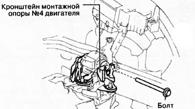
Tighten the nuts shown in the illustration to center the engine mount bracket slots.
Note: If the threaded studs are offset from the centers of the slots, they must be centered by moving the engine slightly, then tighten the mounting nuts.
7. Install the front subframe with engine mounting support cushion No.1 (see chapter "Suspension").
8. Attach the following parts:
Front-wheel drive (2WD) only versions: Engine mount bracket #1, engine mount pad #1 and bracket plate.
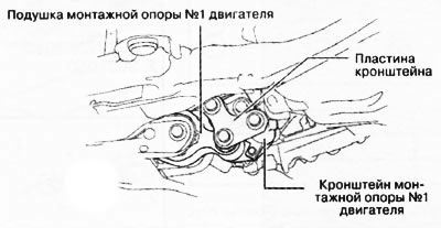
4WD versions: Mounting support pad #1 and bracket plate.
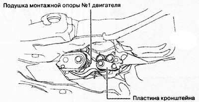
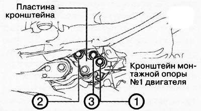
9. Front-wheel drive (2WD) only versions: Tighten engine mounting support bracket No.1 and bracket plate mounting bolts in the sequence shown in the figure to a torque of 84-98 Nm.
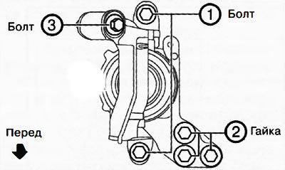
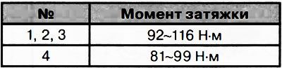
10. Tighten the mounting bolts and nuts of engine mounting support No.3 in the sequence shown in the figure.
 |
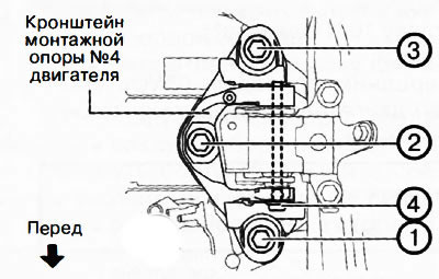 |
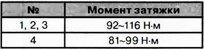
11. Tighten the mounting bolts and nuts of engine mounting support bracket No.4 in the sequence shown in the figure.
 |
 |
12. Tighten the engine mounting support cushion No.1 mounting bolts.
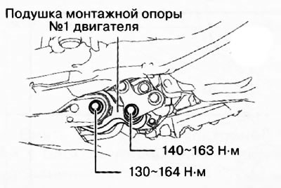
Front-wheel drive (2WD) versions only
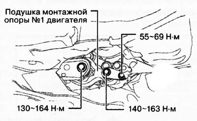
All-wheel drive (4WD) versions
13. Fill the gearbox with the appropriate transmission oil (mechanical or automatic).
14. Fill the engine cooling system.
15. Check the wheel alignment angles of the vehicle (see chapter "Suspension").
16. Start the engine and check the following:
- Presence of leaks of engine oil, coolant, transmission oil and fuel.
- Wobbling or binding of pulleys and drive belts.
- Ignition timing and idle speed.
- Functioning of all engine components.
Note: After installing the engine on the vehicle, it is necessary to perform a test drive to ensure that there are no extraneous noises or vibrations.