


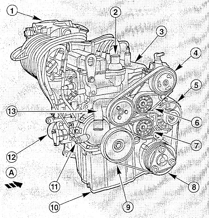
A. Direction of movement; 1. Intake manifold; 2. Thermostat housing; 3. Exhaust manifold; 4. Power steering pump; 5. Generator; 6. Intermediate roller; 7. Belt tensioner; 8. Air conditioning compressor; 9. Crankshaft pulley; 10. Oil pan; 11. Camshaft position sensor; 12. Oil pump; 13. Water pump.
The engine is removed together with the gearbox downwards. A lift or winch is needed to remove the engine.
Since some connections at the bottom of the car need to be loosened during removal, the car needs to be jacked up and supported with four stands. Before starting work in the engine compartment, the fenders need to be covered with a piece of protective fabric.
Depending on the year of manufacture and vehicle configuration, electrical wires, vacuum and coolant hoses may be located in the engine compartment differently. To avoid confusion during subsequent installation, all necessary wires and hoses should be marked before removal. Special instructions for the Ford KA model are provided at the end of the section.
Additional tools and accessories required:
- Steering rod joint puller.
- Winch with towing device or mounting stand.
- Belts for fastening the engine to the mounting stand.
- Molybdenum disulfide (MoS2) based grease.
- Tapes for wire harnesses.
Removal
Disconnect the negative cable from the battery with the ignition off.
Note: This will erase the data from the electronic memory blocks. See the instructions in the chapter "Electrical equipment".
Remove the battery.
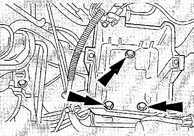
Unscrew the bolts and remove the battery tray.
Drain the coolant.
Remove the fan/thermal switch plug on the bottom left of the radiator.
Loosen the intake pipe clamps on the air filter and intake manifold, remove the intake pipe.
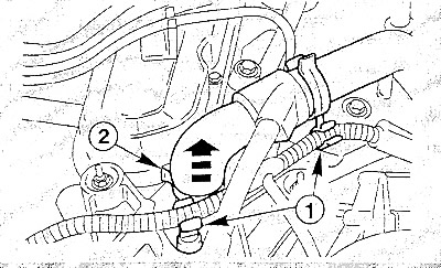
Remove the following coolant hoses from the engine by first squeezing the clamps with a special tool or combination pliers and sliding them back:
- hose (2) from the radiator to the thermostat housing. Release the wire clamp (1) as shown in the figure;
- hose at the top of the radiator;
- two hoses on the radiator at the bottom right;
- hose on the water pump.
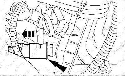
Tighten the heater hose on the coolant manifold by squeezing the quick-release coupling with your hand.
Disconnect the gas cable (rod) from the throttle body and from the support, put it aside.
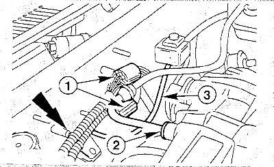
Remove the electrical wires from the engine by cutting the connecting tapes and first marking the positions of the wires.
- Two plugs (1).
- Plug connection for lambda probe (is located in the exhaust manifold).
- Coolant temperature sensor plug on the cylinder block.
- The speed sensor plug is on the engine compartment bulkhead.
- Disconnect the ground wire at the front of the transmission.
- Disconnect the generator wires.
- Disconnect the wires from the starter.
Disconnect the vacuum hose (2) for the brake booster.
Disconnect the vacuum hose (3) for the activated carbon filter system. If necessary, cut the plastic clamp and replace it with a screw clamp during installation.
Remove the oil filler plug. Remove the crankcase ventilation hoses from the oil filler neck. Put the plug back on.
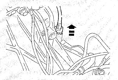
Unscrew the speedometer drive shaft from the gearbox.
Raise and support the vehicle.
Remove the lower engine compartment cover.
Remove the V-belt.
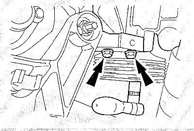
Remove the three bolts securing the power steering pump to the bracket through the pulley holes. The top two bolts are shown in the figure.
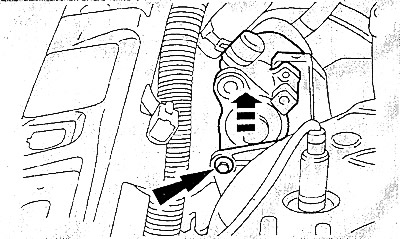
Unscrew the power steering pump mounting bolt from the rear side and attach the pump to the body with wire.
Note: Hoses remain connected.
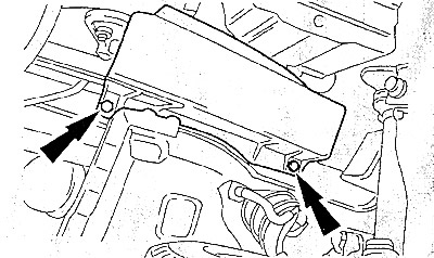
Remove the lower V-belt cover.
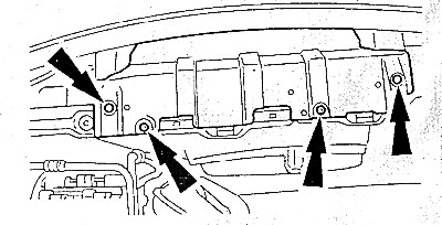
Unscrew the bolts and remove the lower radiator cover.
Cars with air conditioning
Warning: The air conditioning system refrigerant line must not be opened. Refrigerant may cause frostbite if it comes into contact with skin.
In order to be able to remove the engine without opening the coolant line, you need to do the following.
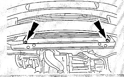
- Unscrew the bolts and remove the air conditioning condenser from the radiator.
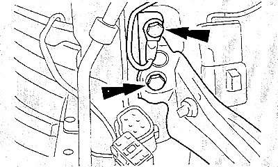
- Unscrew two radiator crossmember bolts on both sides.
- Carefully remove the radiator and radiator fan downwards.
- Secure the capacitor to the body with wire - it remains in the car.
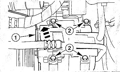
- Remove the plug (1) from the air conditioning compressor. Unscrew the air conditioning compressor bolts together with the holder (2) and secure it to the body with wire so that the refrigerant lines and hoses are not stretched.
Caution: Do not twist, kink or bend the air conditioning system pipes and hoses.
Remove the front exhaust pipe.
Engage fourth gear on the gearbox.
Remove the shift rods from the gearbox.
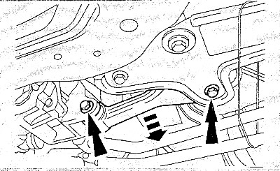
At the bottom (underbody) of the car, unscrew the bolts and remove the spacer between the engine and the power unit mount.
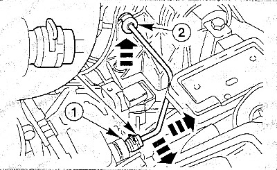
Disconnect the hydraulic line from the clutch slave cylinder on the gearbox. To do this, pull out the fastening bracket at the connection (1) and pull out the line. Pull the line out of the guide (2).
Caution: Collect leaking brake fluid with a rag. The specifics of handling brake fluid are described in the chapter "Brake system".
Plug the open pipe with a stopper or cap to prevent dirt from getting inside.
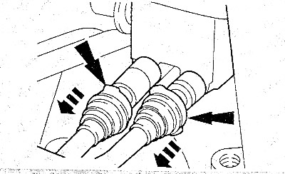
Remove the fuel supply and return hoses from the fuel distributor by squeezing the quick-release coupling with your hand. To avoid confusion, mark the hoses with adhesive tape.
Warning! The fuel system is under pressure! Before loosening the hose connections, place thick rags under them. This will allow you to safely remove the hoses. When doing this, wear protective glasses.
Remove both drive shafts.
Place the assembly table (stand) under the engine, placing wooden blocks between the table and the power unit.
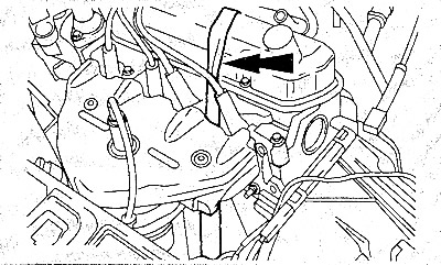
Secure the engine with a belt to the assembly table (stand).
If there is no assembly table, then hang the engine on a chain on a lifting device.
Raise the engine so that the engine mounts are relieved of load.
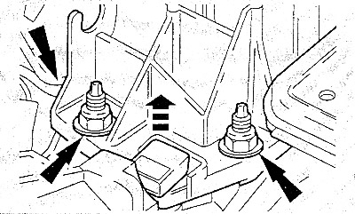
Loosen the mounting bolts on the left support (mount) of the power unit (from the gearbox side).
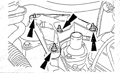
Unscrew the bolts securing the right engine support.
Carefully lower the power unit.
Check that all hoses and wires that go from the engine to the body are disconnected.
Attention! Lowering the engine must be done very carefully, so as not to damage the body detna-li!
Lower the power unit down from the engine compartment.
Installation
Check coolant, oil and fuel hoses and engine mounts for pores and cracks and replace if necessary.
If the car has a high mileage, separate the engine and gearbox, check the driven clutch disc for lining thickness and their general condition. In case of premature wear or high mileage, the clutch must be replaced completely.
Check the release bearing in the slave cylinder for wear and replace it if necessary.
Clean the input shaft splines and lightly lubricate them with MoS based grease.
Check whether there are guide bushings for centering the engine and gearbox in the cylinder block and, if necessary, insert these bushings.
Connect the engine and gearbox. At the same time, turn the primary shaft of the gearbox so that it enters the clutch and the flywheel. You can also turn the crankshaft by its central bolt.
Tighten the engine/gearbox connecting bolts to 45 Nm.
Carefully lift the power unit into the engine compartment, while guiding the engine in the desired direction.
Tighten the new nuts on the left and right engine mounts.
Caution: Nuts on left engine mount (from the gearbox side) tighten by hand 5-6 turns, without tightening yet.
Tighten the right engine mount nuts to 70 Nm.
Disconnect the lifting device from the engine.
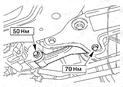
Tighten the strut bolts on the mount to a torque of 70 Nm, on the gearbox - to a torque of 50 Nm.
Align the engine mounts by vigorously rocking them so that they are installed without stress.
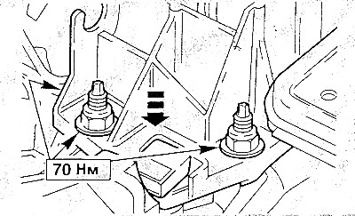
First tighten the left engine mount nuts (from the gearbox side) torque of 70 Nm.
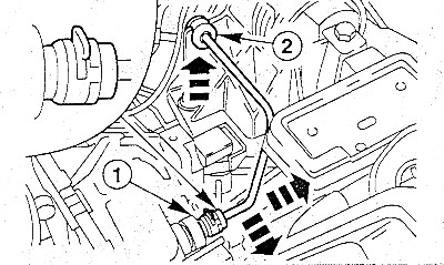
Install the hydraulic line on the clutch slave cylinder. To do this, pull out the fastening bracket in the connection (1), push the line in and reinsert the bracket. Press the line into the guide (2).
Install both drive shafts.
Install the shift rods on the transmission and adjust the shift mechanism.
Install the front exhaust pipe.
Install the radiator.
Cars with air conditioning: secure the condenser to the radiator with two bolts, tightening them to a torque of 15 Nm. Secure the compressor to the engine with four bolts, tightening them to a torque of 25 Nm.
Place the coolant hoses on the engine and heater and secure them with clamps.
Remove the wire and secure the power steering pump to the bracket with four bolts, tightening them to a torque of 25 Nm.
Install V-belts.
Install the lower V-belt cover.
Install the speedometer drive cable to the gearbox.
Lower the car.
Connect all electrical wires to the engine and gearbox. Secure the wires in the holders at the previously marked locations.
Install and secure the fuel supply and return hoses to the fuel distributor.
Attention! To avoid confusion during installation, use the previously applied marks.
Install all vacuum hoses, securing them with clamps if necessary.
Place the crankcase ventilation hoses onto the oil filler neck.
Place the air intake hose onto the air filter and intake pipe and secure with clamps.
Attach the gas control cable (rod) to the throttle body and to the support and adjust it.
Install the battery tray and secure it with three bolts (tightening torque - 25 Nm).
Install the battery.
Check the oil level in the engine and gearbox and top up if necessary.
Check the concentration of the coolant and add it to the system.
Remove air from the clutch hydraulic system.
Install the lower engine compartment cover.
Start the engine and warm it up to operating temperature, monitoring it using the coolant temperature gauge.
Finally, drive at least another 5 km to ensure that the required temperature has been reached.
Check the tightness of all hose connections.
Set the clock readings, enter codes into the radio receiver.
Especially for Ford KA
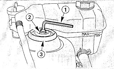
Loosen the lock nut (2) on the shock absorber support (3) on the left and right by five turns, while holding the shock absorber rod with a hex key (1). Tightening torque during installation - 50 Nm.
Remove the air filter housing.
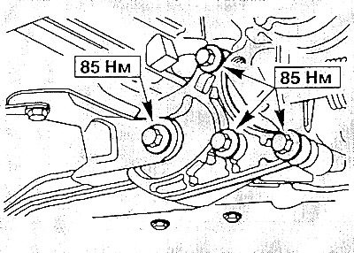
Unscrew the spacer bolts on the gearbox and on the holder.
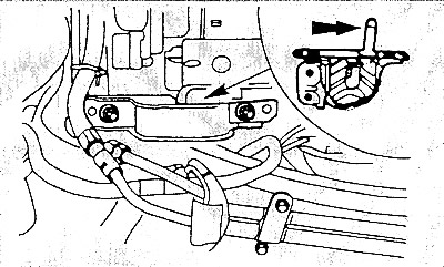
Unscrew the two mounting nuts and remove the left gearbox support.
Note: When installing, the protrusion (arrow) on the support must fit into the corresponding recess.
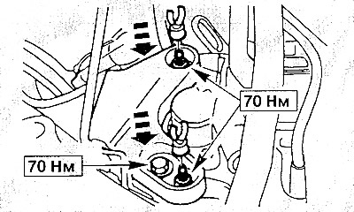
Unhook the wire holder and unscrew one bolt and two nuts of the right engine mount.
Lower the engine until the coolant hose on the water pump can be removed. Remove the hose, then lower the engine completely.