
It is recommended to mark all electrical cables and vacuum lines with adhesive tape before disconnection so that they can be easily reconnected to their original places during installation.
Depending on the year of manufacture and equipment, electrical wires or vacuum and water hoses can be routed differently in the engine compartment. Since it is not possible to describe all the individual options, it is recommended to mark the relevant pipelines and wires with adhesive tape before switching off. The following chapter will describe the removal and installation of a 1.4 liter gasoline engine with a fuel injection system.
Removing
B6 injection engine with injection system
1. Disconnect the battery, follow the instructions, see Section Removing and installing the battery.
2. Unscrew the battery holder.
3. Remove the air filter, see chapter Removal and installation of the air filter.
4. Drain the coolant and remove the radiator with a fan, see Chapter Engine cooling system.
5. Drain gear oil, see chapter Maintenance.
6. Remove the hood, see chapter Body, car painting, car care.
7. Remove the gas drive.
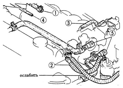
8. Disconnect the vacuum brake hose -1- after loosening the clamp.
9. Loosen clamps and disconnect fuel hoses -2-. When disconnecting, place a rag around the fuel line so that fuel cannot splatter when loosened. Close the pipelines immediately with suitable plugs. To do this, insert, for example, clean bolts of the appropriate diameter into the holes. To facilitate installation, mark the fuel lines with adhesive tape.
10. Disconnect the ventilation vacuum hose -3-.
11. If fitted, disconnect vacuum hose -4- for tempostat.
Carbureted engine
1. Loosen the clamps and disconnect the fuel hoses of the mechanical fuel pump. When disconnecting, place a rag around the fuel line so that fuel cannot splatter when loosened. Close the pipelines immediately with suitable plugs. To do this, insert, for example, clean bolts of the appropriate diameter into the holes. To facilitate installation, mark the fuel lines with adhesive tape.
2. Disconnect the vacuum hoses to the carburetor. To facilitate installation, mark the hoses with adhesive tape.
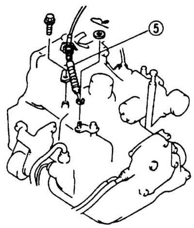
3. Disconnect the heater hoses -5- after loosening the clamps.
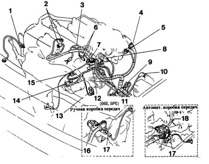
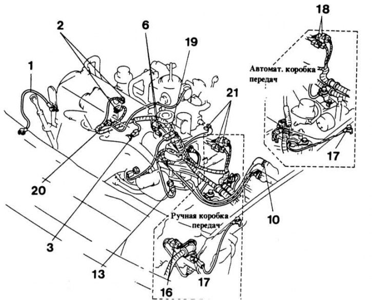
4. Disconnect all electrical connections from the engine. To facilitate installation, pre-mark the wires with adhesive tape.
- Unscrew earth cable -1- at engine.
- Disconnect the generator connections -2-, to do this, unscrew the thick cable B+ and disconnect the plug.
- Disconnect plug for oil pressure sender -3-.
- Unplug combo connector for throttle valve sensor -4- and idle speed controller -5-.
- Disconnect starter connections -6- by unscrewing the thick cable and pulling out the combination plug.
- Disconnect connector -7- for lambda probe.
- Unplug combination connector for injection valves -8-.
- Disconnect plug -9- for neutral sensor (only manual transmission).
- Disconnect terminal 4 -10- at ignition coil.
- Unscrew earth cable -11- at engine.
- Disconnect combination plug -12- at ignition distributor.
- Disconnect combination plug from temperature switch -13- for coolant.
- Disconnect plug -14- for coolant temperature sender.
- Disconnect earth connector -15-.
- Disconnect combination plug -16- at reverse gear switch (only manual transmission).
- Unscrew earth cable -17- at gearbox.
- Disconnect combination plug -18- for starter switch.
- Disconnect plug -19- for temperature sensor.
- If fitted, disconnect plug -20- for starter automatic preheater.
- Disconnect combination plug -21- from carburetor.
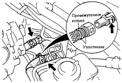
5. Models since 10/89.: Press the nose -arrow- of the hose clamp and detach the heater hose.
Attention! The fitting has an O-ring and an intermediate ring, do not lose them during installation.
6. Raise the car.
7. If available, remove the lower trim of the engine compartment.
Vehicles with power steering (servo control)
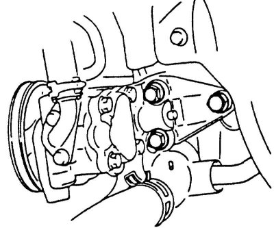
1. Remove the V-belt from the servo pump, see Section Removing and installing/tensioning the V-belt.
2. Unscrew the pump with holder and hang it on a wire with connected hoses so that the pump does not interfere with further removal and the hoses are not taut.
Cars with air conditioning
Attention! The air conditioning circuit must not be opened. The refrigerant contains substances that can cause frostbite if it comes into contact with the skin. The engine can be removed without opening the circuit of the air conditioning system.
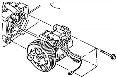
1. Remove the V-belt, see Section Removing and installing/tensioning the V-belt.
2. Unscrew the air conditioning compressor with holder and hang it on a wire with connected hoses so that it does not interfere with further removal and the hoses are not stretched.
Manual Transmission
1. Disconnect the shift rod and extension rod on the gearbox, see Section Removal and installation of a transmission.
2. Hydraulic clutch models: Unscrew clutch slave cylinder with hydraulic line and set aside so that it does not interfere with further removal, see also Chapter Clutch.
Attention! The hydraulic piping remains connected, otherwise the system will need to be bled after installation. When the slave cylinder is removed, do not press the clutch pedal. On some models, the clutch line is removed after the engine mount has been removed.
3. Cable operated clutch models: Disconnect the clutch cable, see Chapter Clutch, Chapter Clutch pedal/cable adjustment.
4. Automatic transmission: Remove the cotter pin and disconnect the shift cable from the gearbox. Unscrew the cable mount on the gearbox.
5. Remove the speedometer shaft, see Chapter Manual transmission.
6. To unscrew a reception pipe of the muffler from a final collector, see the Head Exhaust system.
7. Remove drive shafts, see Chapter Suspension and steering system, Chapter Removal and installation of a power shaft.
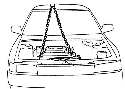
8. Attach a suitable chain to the engine lugs and lift the engine to relieve the engine mounts.
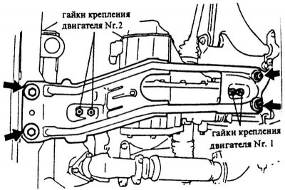
9. To unscrew nuts of fastening of the engine No. 1 and No. 2.
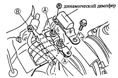
10. Unscrew the dynamic damper and fastening nuts -A-.
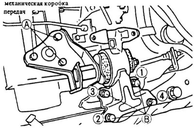
11. Unscrew the nut -B-, remove the bolt and remove the engine support.
12. Unscrew the mounting bolts -A- and -B- of the engine support on the side of the gearbox and remove the support complete with holder.
13. Check if all hoses leading from the engine to the body are removed. Then take out the engine with the crane up.
Attention! Guide the engine carefully when lifting to avoid damage to the bodywork.
14. Remove the gearbox from the engine, see Chapter Manual transmission, Chapter Removal and installation of a transmission.
Installation
1. Check engine mounts, water, oil and fuel hoses for cracks and breaks, replace if necessary.
2. Check the ease of movement of the release bearing and the clutch release lever, replace if necessary.
3. Check the thickness and condition of the clutch disc friction lining, replace if necessary.
4. Clean the clutch shaft spline and lubricate with MoS2 grease.
5. Attach the gearbox to the engine, see Chapter Manual transmission.
6. Carefully insert the engine from above into the engine compartment using a crane. When lowering, make sure that the bolts of the lower engine mounts enter the holes in the beam.
7. Install the nuts securing the lower engine mounts.
8. To establish bolts of fastening of the top support of the engine. On some models, before installing the supports, it is necessary to lay the pipeline to the clutch slave cylinder.
9. Align the engine.
10. Tighten the fastening nuts on the lower engine mounts with a force 70 Nm until 9/89 of issue; with effort 50 Nm since 10/89 issue.
11. Tighten the fastening nuts -A- of the engine support with a force 80 Nm.
12. Tighten nut -B-. Tightening torque: up to 9/89 MY 60 Nm, starting from 10/89, issue. 80 Nm.
13. If available, screw in the dynamic damper with force 70 Nm.
14. Models since 10/89: Tighten the engine mounting bolts -B- in the order shown from 1 to 4 to 50 Nm. Tighten nuts -A- 80 Nm.
15. Install drive shafts, see Chapter Suspension and steering system, Chapter Removal and installation of a power shaft.
16. Install the muffler downpipe and exhaust pipe or catalytic converter.
Manual Transmission
1. Attach the shift rod and extension rod on the gearbox. Screw the extension rod firmly 40 Nm, switching bar with force 20 Nm.
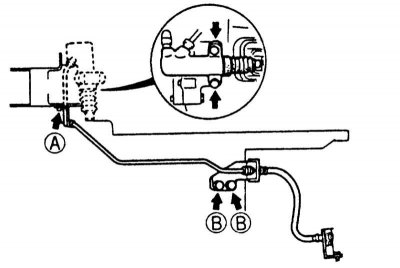
2. Models with hydraulic clutch actuation: Install clutch slave cylinder with hydraulic line and tighten bolts -B- 20 Nm, -A- with effort 10 Nm.
3. Tighten the clutch slave cylinder bolts with force 20 Nm.
Cable operated clutch models
1. Install the clutch cable, see Chapter Clutch, Chapter Clutch pedal/cable adjustment.
2. If available, install the lower trim of the engine compartment.
3. Lower the car.
4. Install and adjust the gas actuator, see Chapter Power system, carburetor, fuel injection system, Chapter Check/removal and installation of automatic cold start.
5. Install the speedometer shaft.
Automatic transmission
1. Attach the shift cable to the gearbox and insert the cotter pin. Tighten the cable mount on the gearbox with a force 10 Nm.
Vehicles with servo control
1. Install the pump with holder and screw firmly 50 Nm.
2. Install the servo pump V-belt, see Section Removing and installing/tensioning the V-belt.
Cars with air conditioning
1. Install the air conditioning compressor with holder and screw firmly 30 Nm.
2. Install the A/C compressor V-belt, see Section Removing and installing/tensioning the V-belt.
3. Connect and screw all electrical wires and vacuum hoses according to the marked marks.
4. Put on the heater hoses and, depending on the model, secure with clamps.
5. Connect the supply and return fuel lines and secure with hose clamps.
6. Install the radiator, see Chapter Engine cooling system, Removal and installation of a radiator.
7. To fill in oil in the engine and a transmission, see the Head Maintenance.
8. Check the coolant for frost resistance and fill it in, see Chapter Engine cooling system, Chapter Coolant replacement.
9. Install the air filter, see chapter Removal and installation of the air filter.
10. Install the hood, see Chapter Body, car painting, car care, Chapter Removing and installing/adjusting the hood
11. Screw the battery holder firmly 20 Nm.
12. Install battery, see chapter Electrical system, Chapter Removing and installing the battery.
13. If required, adjust the valve clearance, see Section Checking/adjusting valve clearance.
14. Check the ignition timing, adjust if required, see Chapter Ignition system, Chapter Checking / adjusting the ignition timing.
15. Check idle speed, adjust if necessary, see Chapter Power system, carburetor, fuel injection system.
16. Warm up the engine, check the coolant level and the tightness of all connections.