
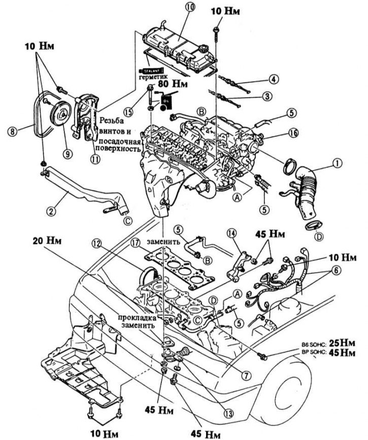
1 - air hose; 2 - resonance chamber; 3 - gas drive; 4 - throttle actuator (only with automatic transmission); 5 - hoses; 6 - cable harness; 7 - nut, bypass pipeline of the cooling system; 8 - V-belt; 9 - belt pulley of the water pump; 10 - cylinder head cover; 11 - the upper casing of the toothed belt; 12 - toothed belt; 13 - exhaust pipe of the muffler; 14 - intake manifold mounting; 15 - cylinder head bolts; 16 - cylinder head; 17 - cylinder head gasket
When removing the cylinder head, the engine must be cooled to at least room temperature. The exhaust and intake manifolds remain connected. Removal is described for VZ, V5, V6 and BP engines. At the end of the chapter are instructions for the diesel engine. Differences for motor series E are indicated in a separate chapter, see Section Removal and installation of the camshaft / adjustment of the valve timing.
A failed cylinder head is identified by one or more of the following:
- Loss of power.
- Loss of coolant. White exhaust clouds on a warm engine.
- Oil loss.
- The coolant in the engine oil, the oil level does not decrease, but increases. Gray engine oil, traces of foam on the dipstick, the oil is diluted.
- Engine oil in coolant.
- The coolant boils a lot.
- There is no compression in two adjacent cylinders.
Removing
B6 engine with injection system
1. Disconnect the ground cable from the battery.
Attention! This erases the data from the engine fault memory or the radio's security code. Before disconnecting the battery, read the instructions in Section Removing and installing the battery.
2. injection engine: Loosen the clamps and remove the intake hose.
3. Carburetor engine: Remove air filter, see chapter Power system, carburetor, fuel injection system, Chapter Removal and installation of the air filter.
4. If present, remove resonance chamber.
5. Drain the coolant, see Chapter Maintenance.
6. Remove the gas actuator, see Chapter Power system, carburetor, fuel injection system, Chapter Check/removal and installation of automatic cold start.
7. Automatic transmission: Disconnect the throttle cable.
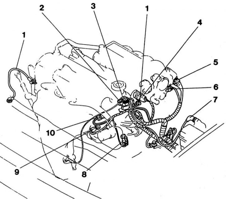
8. Disconnect all electrical wires to the cylinder head. To facilitate installation, the wires should be pre-marked with adhesive tape.
- Unscrew earth cable -1- at engine.
- Disconnect connector -2- for lambda probe.
- Disconnect combination plug -3- at ignition distributor.
- Disconnect combination plug -4- for injection valves.
- Disconnect combined connector for throttle valve sensor -5- and idle speed controller -6-.
- Disconnect terminal 4 -7- on the ignition coil.
- Disconnect combination plug -8- for coolant temperature switch.
- Disconnect plug -9- for coolant temperature sender.
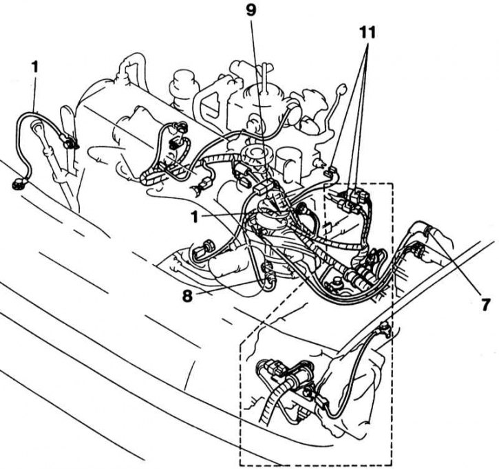
- Disconnect earth cable -10- at engine.
- Disconnect combination plugs for carburetor connections -11-.
9. Disconnect the vacuum brake hose after loosening the clamp.
Injection engine
1. Loosen hose clamps and disconnect fuel hoses -2-. When disconnecting, lay a rag around the fuel lines so that fuel does not splatter when loosened. Seal the pipelines immediately with suitable plugs, eg clean bolts of the appropriate diameter. To facilitate subsequent installation, mark the fuel lines with adhesive tape.
2. If fitted, disconnect vacuum hose -4- for tempostat.
3. Disconnect the ventilation vacuum hose -3-.
Carbureted engine
1. Loosen the hose clamps and disconnect the fuel lines at the mechanical fuel pump. When disconnecting, lay a rag around the fuel lines so that fuel does not splatter. Seal the pipelines immediately with suitable plugs, eg clean bolts of the appropriate diameter. To facilitate subsequent installation, mark the fuel lines with adhesive tape.
2. Disconnect the hose from the intake air heating control by loosening the clamp.
3. Disconnect the heater hoses -5- after loosening the clamps.
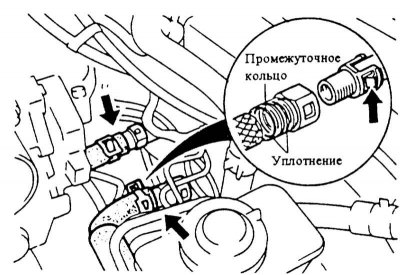
4. Models since 10/89: Press tab -arrow- on hose clamp and detach heater hose.
Attention! The fitting has an O-ring and an intermediate ring. Don't forget them when installing.
5. To unscrew a nut of fastening of a bypass pipeline of system of cooling and to disconnect a bracket.
6. Remove toothed belt, see Sections Removal and installation of a gear belt of VZ, V5, B6 engines (SOHC), VR (SOHC), Removal and installation of a gear belt (DOHC).
7. To unscrew a cover of a head of cylinders.
8. To unscrew a reception pipe of the muffler from a final collector, see the Head Exhaust system.
9. injection engine: Remove the intake manifold bracket.
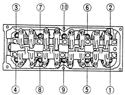
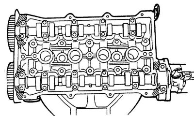
10. Loosen the cylinder head bolts in sequence 1 to 10 in the first pass by 1/2 turn, in the second pass by one full turn, and completely unscrew on the third pass.
Attention! Loosening the cylinder head bolts in the wrong order can result in deformation or cracks in the cylinder head.
11. Check that all hoses from the cylinder head to the engine and body are disconnected.
12. Remove the cylinder head with the help of an assistant.
Attention! Do not place the cylinder head on the sealing surface after removal, otherwise fully open valves may be damaged. Lay the cylinder head on two wooden blocks.
Installation
1. Before installation, clean the block and cylinder head from seal residues with a scraper. In doing so, the sealing surfaces must not be scratched. Make sure that seal residues do not fall into the cylinders. Cover holes with a cloth.
2. Check that there is no oil in the cylinder head bolt holes; if necessary, remove the oil with compressed air. If compressed air is not available, you can clean the holes with a small screwdriver wrapped in a rag.
Attention! In any case, the oil must be removed.
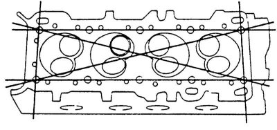
3. Check the cylinder head for deformation with a steel ruler and feeler gauge.
4. Check for deformation in the indicated directions. The maximum allowable unevenness is 0.15 mm. If the limit value is exceeded, the cylinder head must be machined (performed in the workshop).
5. Check the cylinder head for cracks. If there are cracks, the head must be replaced.
6. Check water, oil and fuel hoses for cracks and breaks, replace if necessary.
7. Check valves and valve guides for wear and damage.
8. Apply the cylinder head gasket so that the holes in the cylinder block and the gasket match.
9. Apply a small amount of oil to the contact surfaces and threads of the cylinder head bolts.
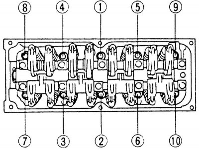
10. Screw in 10 bolts until they touch the cylinder head by hand. Then the bolts should be tightened in three passes. On each pass, the bolts are tightened in sequence from 1st to 10th.
- 1st pass: 40 Nm
- 2nd pass: 60 Nm
- 3rd pass: 80 Nm
Attention! Cylinder head bolts must be tightened very carefully. Before tightening, check the accuracy of the torque wrench. In addition, the tightening sequence must be followed exactly.
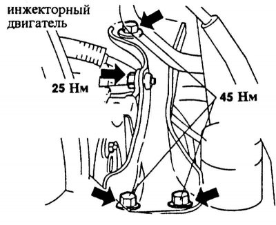
11. injection engine: Tighten the intake manifold fasteners 25 Nm and 45 Nm.
12. Screw the exhaust pipe of the muffler to the exhaust manifold with force 45 Nm.
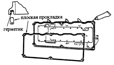
13. DOHC Engine: Apply silicone-based sealant to the shaded areas (e.g. DOW CORNING Q3-7057). Install a new valve cover gasket.
14. SOHC engine: Apply silicone-based sealant to the gasket groove in the cylinder head cover (e.g. DOW CORNING Q3-7057). Install a new cover gasket.
15. Install the cylinder head cover and screw firmly 10 Nm.
16. Install toothed belt, see Sections Removal and installation of a gear belt of VZ, V5, B6 engines (SOHC), BP (SOHC), Removal and installation of a gear belt (DOHC).
17. Install the bypass pipeline of the cooling system and tighten the fastening nut with force 20 Nm.
18. Install and adjust the gas actuator, see Chapter Power system, carburetor, fuel injection system, Chapter Check/removal and installation of automatic cold start.
19. Connect all electrical wires and vacuum hoses as marked.
20. Put on the heater hoses, and, depending on the model, snap or secure with clamps.
21. Connect the supply and return fuel lines and secure with clamps.
22. Install the air filter, see Chapter Power system, carburetor, fuel injection system, Chapter Removal and installation of the air filter.
23. Check the frost resistance of the coolant and fill it into the system, see Chapter Maintenance.
24. Connect the battery ground cable.
25. If available, set the clock and set the radio security code.
26. Change engine oil, see chapter Maintenance.
27. Check the ignition timing, if required, adjust, see Chapter Ignition system, Chapter Checking / adjusting the ignition timing.
28. Check idling, adjust if necessary, see Chapter Power system, carburetor, fuel injection system.
29. Warm up the engine, check the coolant level and the tightness of all hose connections.
30. If required, check valve clearance, see Section Checking/adjusting valve clearance.
Diesel engine
Removing
1. Remove the battery and unscrew the battery holder, see chapter Electrical system, Chapter Removing and installing the battery.
2. Remove the air filter, see chapter Power system, carburetor, fuel injection system, Chapter Removal and installation of the air filter.
3. Remove the injection lines, see Chapter diesel engine.
4. Unscrew the supply and return pipes.
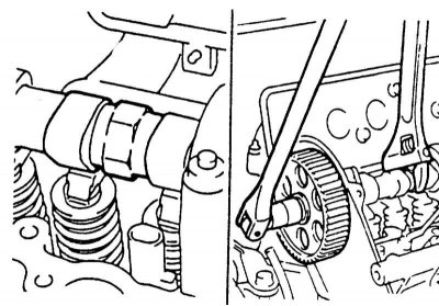
5. Holding the camshaft with an adjustable wrench, for example, HAZET 279-15, unscrew the bolt securing the camshaft gear. Remove the camshaft wheel, if necessary knock it down with light blows of a rubber mallet.
Attention! When holding the camshaft, do not damage the cylinder head with a wrench.
6. To unscrew a back casing of a gear belt.
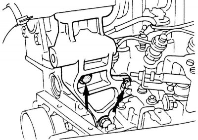
7. Unscrew the bolts -arrows- for the front engine mount.
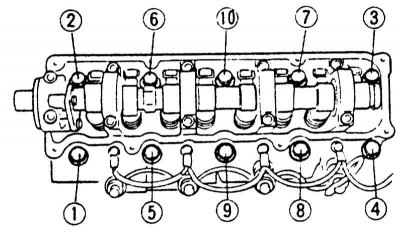
8. Loosen the cylinder head bolts in sequence 1 to 10 in the first pass by 1/2 turn, in the second pass by one full turn, and back out completely on the third pass.
Attention! Loosening the cylinder head bolts in the wrong order can result in deformation or cracks in the cylinder head.
Installation
1. Check the cylinder head for deformation. The maximum allowable deformation on the sealing surface can be 0.1 mm. If the deformation exceeds the limit value, the cylinder head must be machined (performed in the workshop).
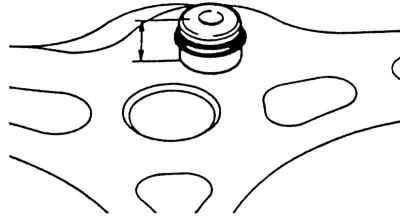
2. Measure the protrusion of the plug. Required value: 7 - 8 mm. If necessary, tap the plug with a hammer to the specified size. Cover by new seal the O-ring with a small amount of oil and insert it into the groove of the plug.
3. Measure the length of the cylinder head bolts from the lower edge of the head to the end of the rod. The maximum length of 114.5 mm must not be exceeded. If the value does not meet the requirement, the bolt must be replaced.
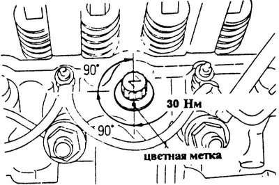
4. Screw in the 10 cylinder head bolts by hand until they are in contact with the head. Then tighten the bolts in three passes. On each pass, the bolts are tightened in the sequence shown in the illustration from 1st to 10th.
1st pass: torque wrench with force 30 Nm
2nd pass: tighten 1/4 turn with a hard wrench without removing the wrench
3rd pass: tighten 1/4 turn with a hard wrench without removing the wrench
5. Screw on the front engine mount with a force 45 Nm.
6. Install the rear toothed belt guard and screw firmly 10 Nm.
7. Install gear and wedge. To tighten the mounting bolt, hold the camshaft with a wrench. Torque: 50 Nm.
8. Install toothed belt, see Chapter diesel engine.
9. Install the fuel supply and return lines, as well as the injection line, see Chapter diesel engine.
10. Install the air filter, see chapter Power system, carburetor, fuel injection system, Chapter Removal and installation of the air filter.
11. Install the battery holder and screw firmly 10 Nm.
12. Install battery, see chapter Electrical system, Chapter Removing and installing the battery.