
16 valve SOHC engine
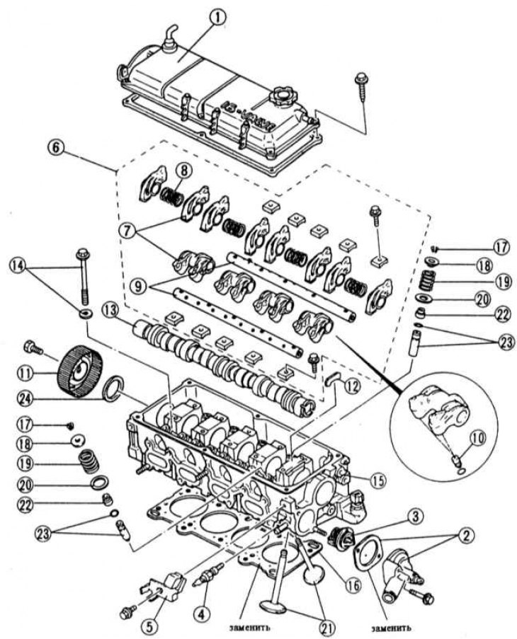
1 - cylinder head cover with gasket; 2 - thermostat housing with gasket; 3 - thermostat; 4 - temperature sensor; 5 - mount; 6 - rocker shafts with rocker arms; 7 - rocker arms; 8 - rocker springs; 9 - rocker shafts; 10 - hydraulic valve lifters (Only on engines with hydraulic valve clearance compensation.); 11 - camshaft gear; 12 - pressure plate; 13 - camshaft; 14 - cylinder head bolt; 15 - cylinder head; 16 - cylinder head gasket; 17 - valve crackers; 18 - the upper cup of the valve spring; 19 - valve spring; 20 - lower plate of the valve spring; 21 - valve; 22 - oil cap; 23 - valve guide; 24 - stuffing box
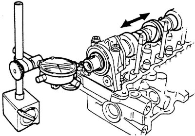
1. Check the end play of the camshaft. Required value:
- Engines B3, B6 (SOHC): 0.04—0.13 mm
- VR engines (SOHC): 0.06—0.20 mm
- Engines B3E, B5, B6E: 0.05-0.18 mm
2. If the values are not correct, replace the thrust plate and possibly also the camshaft.
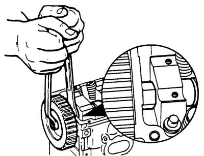
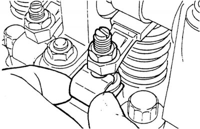
3. While holding the camshaft with a wrench, unscrew the bolt securing the camshaft gear. Remove the gear wheel, if necessary, knock it down with light blows of a rubber hammer.
Attention! Remove the camshaft sprocket carefully so as not to lose the guide pin.
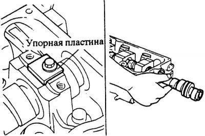
4. To unscrew a persistent plate and to take out a camshaft through an aperture of the distributor.
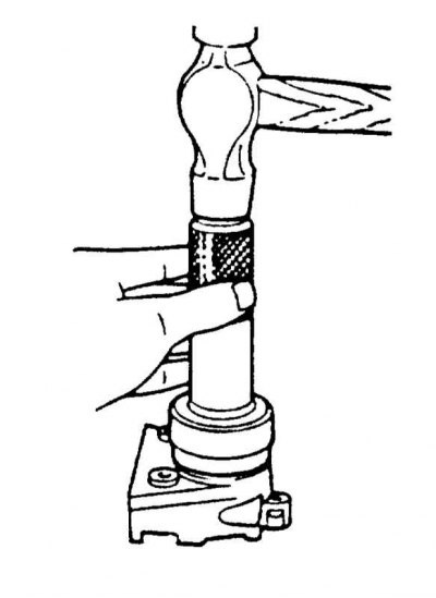
5. Knock out the old camshaft oil seal with a punch.
Attention! In this case, the seat of the gland must not be damaged.
Installation
1. Lubricate the landing site and the camshaft oil seal with a small amount of engine oil. Carefully drive the gland into place using a pipe of the same diameter. Drive in the oil seal so that it is flush with the cylinder head.
Attention! Do not twist the seal during installation.
2. Lubricate all camshaft bearings with a small amount of engine oil.
3. Carefully insert the camshaft into the cylinder head through the distributor bore.
Attention! The shaft must not twist when pushed in. Carefully push through the stuffing box so as not to damage the sealing lip.
4. Install the camshaft so that the pressure plate can fit into the groove of the camshaft. Screw in the thrust plate 10 Nm.
5. Insert the guide pin into the camshaft. Install the camshaft wheel so that the guide pin engages in the groove.
6. While holding the camshaft with a wrench, screw the camshaft gear with force 60 Nm.
Attention! When holding the shaft, do not damage the cylinder head with a wrench.
7. Check if the crankshaft and camshafts are on the ignition marks of the 1st cylinder, adjust if necessary, see Section Removal and installation of camshafts.
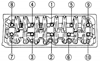
8. Tighten the bearing cap bolts with a torque wrench in the sequence shown. The bolts must be tightened in two passes.
- 1st pass: 15 Nm
- 2nd pass: 25 Nm
9. Clean the camshaft wheel from water and oil.
10. Install and tighten the toothed belt, see Section Removal and installation of a gear belt of VZ, V5, B6 engines (SOHC), VR (SOHC).
11. If available, install a mechanical fuel pump on the cylinder head, see Chapter Power system, carburetor, fuel injection system, Chapter Removal and installation/check of the fuel pump.
12. If the engine is not equipped with hydraulic tappets, check the valve clearance, see Section Checking/adjusting valve clearance.
13. Install the cylinder head cover with gasket, see Section Removal and installation of the cylinder head / replacement of the cylinder head gasket.
14. Install the air filter, see Chapter Power system, carburetor, fuel injection system, Chapter Removal and installation of the air filter.
15. Screw the battery holder firmly 20 Nm.
16. Install the battery, see Section Removing and installing the battery.
Removal for 1.7L diesel engine
Attention! With the toothed belt removed, the camshaft wheel must not turn, otherwise the valves will hit the pistons.
1. Remove toothed belt, see chapter diesel engine.
2. To unscrew a back casing of a gear belt.
3. Remove the rocker springs.
4. Mark the rocker arms so they can be reinstalled when installed.
5. Remove the rocker arms from their places.
6. Check the end play of the camshaft. Required value: 0.02-0.18 mm. Maximum allowable axial play: 0.20 mm. If this value is exceeded, the camshaft and possibly the cylinder head must be replaced.
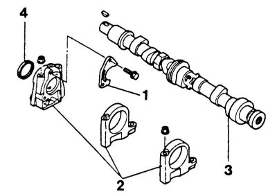
7. Unscrew pressure plate -1-.
8. Unscrew 3 support brackets -2-camshaft and remove together with camshaft -3-.
9. Remove the front support bracket from the camshaft and remove the oil seal -4- with a screwdriver.
Installation
1. Lubricate the landing site and the camshaft oil seal with a small amount of engine oil. Carefully drive the gland into place using a pipe of the same diameter. Drive in the oil seal so that it is flush with the cylinder head.
Attention! Do not twist the seal during installation.
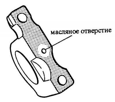
2. Clean the contact surfaces of the support brackets from dirt and oil.
3. Apply sealant, eg Hylomar, to the mounting surfaces.
Attention! Sealant must not be applied to the oil hole.
4. Install the camshaft together with the support brackets.
5. Tighten the mounting bracket bolts with a torque wrench from the inside out. Bolts are tightened in two passes.
- 1st pass: 15 Nm
- 2nd pass: 25 Nm
6. Install stop plate and screw firmly 10 Nm.
7. Install the rocker arms. Make sure that the levers sit correctly in their places.
8. Insert the rocker springs.
9. Install the rear toothed belt cover and screw firmly 10 Nm.
10. Install the key and camshaft gear. To tighten the mounting bolt, hold the camshaft with a wrench. Torque: 50 Nm.
11. Adjust valve clearance, see Section Checking/adjusting valve clearance.