
Coolant circuit
B3, B6, VR (SOHC)
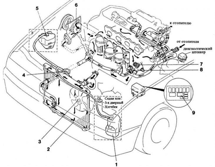
1 - expansion tank; 2 - radiator; 3 - radiator fan; 4 - radiator cap; 5 - expansion tank model F; 6 - water pump; 7 - thermostat; 8 - thermal switch; 9 - fan relay
The cooling system consists of a radiator, water pump, thermostat and electric fan.
The coolant circuit is thermostatically controlled. While the engine is cold, the coolant circulates only in the cylinder block and heater heat exchanger. When the coolant heats up, the thermostat opens and coolant begins to flow through the radiator. The coolant is driven by a water pump, which is in turn driven by a V-belt. The coolant flows through the radiator from top to bottom and is cooled by the air flowing through the plates.
An electric fan provides additional cooling. When the temperature of the coolant rises to + 91°C, the thermal switch turns on the fan through the relay. If the coolant temperature drops below +84°C, the thermal switch automatically turns off the fan.
The coolant reservoir serves as an expansion tank and collects the liquid that expands when heated, and returns it to the circuit after the engine has cooled. As a result, the circuit is constantly filled and provides good cooling. Coolant must be added only through the expansion tank.
Attention! The radiator fan may turn on automatically when the engine is off and the ignition is on. This process, caused by heat in the engine compartment, can be repeated several times. When working in the engine compartment on a hot engine, you should always be aware of the possibility of unexpected activation of the fan. Therefore, whenever possible, when working in the engine compartment, the ignition should be turned off.