


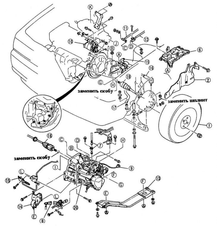
1 - Front wheel 2 - Mudguard 6 - Battery holder 7 - Speedometer shaft 8 - Reversing light plug 9 - Neutral position switch plug 10 - Starter 11 - Shift rod I 12 - Shift rod II 13 - Engine/gearbox support beam 14 - Front engine/gearbox mount 15 - Clutch slave cylinder 16 - Tie rod end 17 - Stabilizer 18 - Drive shaft 19 - Rear engine/gearbox mount 20 - Gearbox
The gearbox is removed downwards. This requires a lift with a platform or 4 reliable supports, as well as a lift with a suitable wooden pad to lower the gearbox. A crane is required to suspend the engine remaining on the car.
Removal
1. Disconnect the ground cable from the battery.
Warning! This will erase the engine fault memory or the radio security code. Before disconnecting the battery, read the instructions in Section Removal and installation the battery.
2. Disconnect the positive battery cable, loosen the fastening and remove the battery.
3. Unscrew and remove the battery holder.
4. Carburetor engine: Remove the air filter, see Chapter Power supply system, carburetor, fuel injection system, Chapter Removal and installation the air filter.
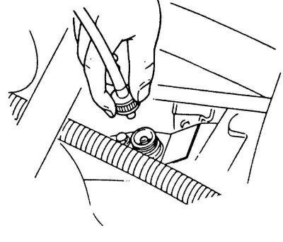
5. Injector and diesel engine: Remove the intake pipe and the intake manifold pre-chamber by loosening the clamps and removing the air hose.
6. Diesel engine: Remove the fuel filter, see Chapter Maintenance.
7. Unscrew the union nut of the speedometer shaft. Remove the speedometer shaft. On vehicles produced since 9/89, unscrew the bolt of the speedometer shaft gear.
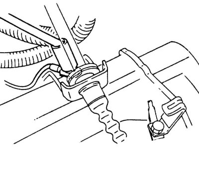
8. Petrol front-wheel drive models up to 9/89 and all station wagon models: Disconnect the cable on the clutch release lever and unscrew the counter support on the gearbox.
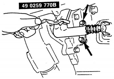
9. Hydraulic drive: Unscrew the clutch slave cylinder on the gearbox housing (2 bolts). Do not loosen the hydraulic lines! Remove the feed line from the mount. Hang the slave cylinder on a wire on the side of the body.
10. Disconnect the reverse light cable on the gearbox.
11. Unscrew the ground cable on the top side of the gearbox.
12. If present, unscrew the guide cable fastenings and the coolant pipe fastening on the gearbox housing.
13. Remove the starter by loosening the bolts. First disconnect the cable and plug on the starter, see also Chapter Electrical equipment system.
14. Loosen the front wheel bolts without unscrewing.
15. Raise the front of the vehicle.
16. Remove the front wheels and unscrew the left side mudguard in the wheel arch.
17. Drain the transmission oil, see Chapter Maintenance.
18. Unscrew both shift rods on the gearbox and hang them on a wire from the bottom.
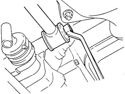
19. Remove the left and right drive shafts. To do this, first remove the tie rod ends, then the lower wishbones on both sides. Finally, press the drive shafts on the inner joints, see Chapter Suspension and steering system, Chapter Removal and installation the drive shaft.
20. Remove (if any) front stabilizer, see Chapter Suspension and steering system.
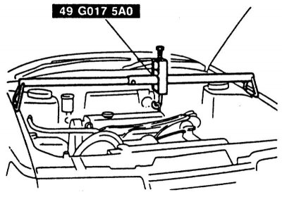
21. Attach a cable to the engine earrings and tighten it slightly, i.e. lift the engine slightly.
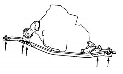
22. Unscrew the gearbox from the center engine mount beam. Then unscrew the beam from the body and remove it.
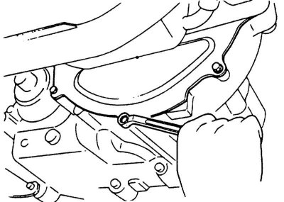
23. Unscrew the clutch cover.
All wheel drive only
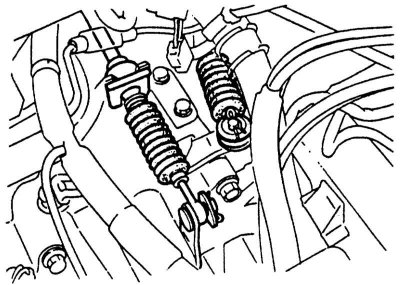
1. Remove the cotter pins and shift rods from the gearbox levers. Remove the brackets on the counter supports.
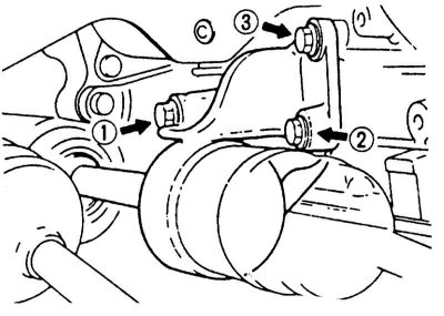
2. Unscrew the bolts of the intermediate shaft support console of the drive shafts.
3. Remove the exhaust pipe and the cross member on the driveshaft tunnel.
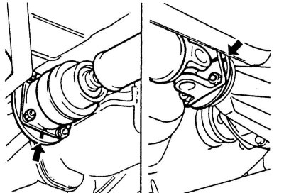
4. Remove the propeller shaft, before loosening the bolts, mark the position of the flanges at the front and rear with a felt-tip pen so that the shaft can be installed in its original position.
5. BP engines only - SOHC (for engine identification see Chapter Petrol engines): Unscrew the differential lock actuator (4 bolts), after turning the shift rod with a screwdriver (is done in the workshop).
6. Unscrew the rear engine mount from the body.
7. Lower the engine/gearbox using the hoist on the left side.
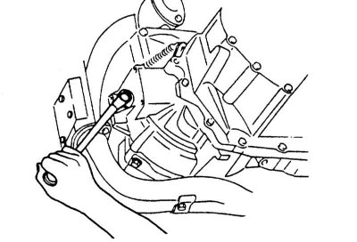
8. Unscrew the front engine mount on the gearbox.
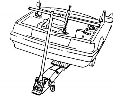
9. Place a lift under the gearbox, using suitable wooden spacers.
10. Remove the 2 flange bolts accessible from above that connect the engine and gearbox. On models up to 1987,. (e engines) instead of 2 there are 4 upper bolts.
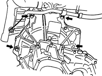
11. Unscrew the lower engine and gearbox mounting bolts from the bottom. On diesel engines, additionally unscrew the 2 corners between the gearbox and the engine from the bottom left and right.
12. Slightly lift the gearbox with your hand and press it away from the engine with a crowbar.
13. Lower the gearbox using a lift and roll it out with the help of an assistant.
Installation
1. Before installing the gearbox, check the clutch and release bearing, see Chapter Clutch.
2. Clean the splined connection of the input shaft and lightly lubricate with molybdenum paste or spray.
Caution! If too much grease is applied, it may come into contact with the friction lining of the driven disk during operation, which will cause malfunctions.
3. Roll the gearbox onto the lift under the vehicle.
4. If, when installing the gearbox, the primary shaft does not enter the driven clutch disc, turn the gearbox shaft slightly (turn on the transmission), or ask an assistant to turn the engine crankshaft a little.
5. Align the gearbox. In most cases, there are guide pins on the engine flange that should fit into the holes in the clutch housing.
6. Insert all mounting bolts and screw the gearbox to the engine. Tighten the bolts with force 90 Nm.
Attention! In this case, do not under any circumstances pull the gearbox to the engine by tightening the bolts. First, tighten all the bolts evenly, and only then tighten them with a torque wrench.
7. Screw the front engine mount onto the gearbox housing, tighten the bolts with force 50 Nm.
8. Install the engine using a hoist in the correct installation position.
9. Screw the middle beam of the engine mount onto the gearbox, tighten the 4 bolts "A" with force 50 Nm.
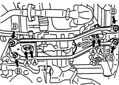
10. Screw the middle beam to the body with force 80 Nm, bolts "B".
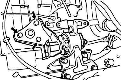
11. Screw the rear engine mount to the body with force 80 Nm.
12. Remove the hoist and engine mount.
13. All-wheel drive only: Align the flanges of the cardan shaft according to the marks, insert the bolts with washers, tighten the nuts with force 30 Nm.
14. All-wheel drive: Install shift rods and exhaust pipe, if necessary install differential lock actuator (is done in the workshop), see paragraph Removal.
15. All-wheel drive: Tighten the intermediate shaft support console bolts of the drive shafts in the given sequence with force 50 Nm.
16. Insert the clutch cover and screw it on. For a diesel engine, additionally screw on the side reinforcement plates.
(The article is reprinted from the portal: Mazbook)
17. Insert the starter and tighten the 3 bolts with force 40 Nm.
18. Connect the plug and cable to the starter.
19. Install both drive shafts with new retaining rings, see Chapter Suspension and steering system, Chapter Removal and installation the drive shaft.
20. Install the stabilizer and tie rod ends, see Chapter Suspension and steering system.
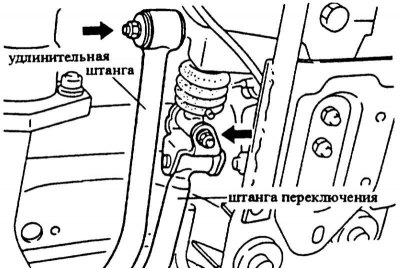
21. Screw the shift rods onto the gearbox. Tighten the so-called extension rod with force 40 Nm, shift rod with force 20 Nm.
22. Screw the mudguard into the left wheel arch.
23. If equipped, screw in the lower engine shield.
24. Fill with transmission oil, see Section Routine maintenance.
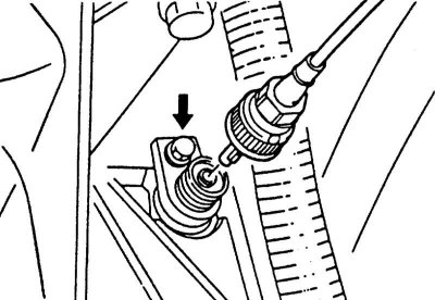
25. Install the speedometer shaft on the gearbox and screw it on with a union nut. On cars from 9/89, first insert the speedometer gear and screw it on with the "arrow" bolt.
26. Screw the clutch slave cylinder onto the gearbox housing, tighten the bolts to 20 Nm. Route the hydraulic lines in the mount on the gearbox. In the version with a cable drive, connect and adjust the clutch cable, see Chapter Clutch, Chapter Adjusting the clutch pedal/cable.
27. Screw on the front wheels and lower the car.
28. Tighten the wheel nuts crosswise with force 100 Nm.
29. Connect the plug to the reversing light switch.
30. Screw on the gearbox ground cable.
31. If equipped, screw the cable holder and coolant pipe mount onto the transmission housing.
32. Install the air filter and air inlet hose, see Chapter Power supply system, carburetor, fuel injection system, Chapter Removal and installation the air filter.
33. Diesel engine: Install the fuel filter.
34. Insert and screw the battery holder.
35. Install and connect the battery, first the positive cable, then the ground cable.
36. If available, set the time on the clock and set the security code for the radio receiver.
37. Measure the wheel alignment angles as soon as possible.